pipemakermike · Nov 06, 2004 11:23 AM
#0 source[photo not recovered: shaft1.jpg]
The shaft seems to have been balanced by removing material from the crankpin area. It also looks to me as though some reshaping of the induction hole has been done.
[photo not recovered: liner1.jpg]
The shape looks a bit complex for a production engine so has it been modified?
[photo not recovered: cylinder_head.jpg]
This looks like a new special part. I guess that the head shape has been changed (has anyone got a picture of the standard item?)
[photo not recovered: head_fins.jpg]
This looks like the old head remachined to accept the new core head.
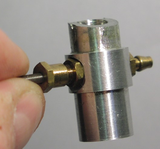
This is a replacement item. It looks a little loose and would benefit from a sealing ring. It is held in with 2 grub screws. The bore is 7.3mm (any comments on this size?)
I also found, when inspection the crankcase that some sort of glue - probably epoxy - had been put at the top of the transfer ports probably to lower them by about 1/16" (ish) The epoxy was quite soft from the action of the oil and some just fell out when I poked it with a cocktail stick.
Question should I replicate this epoxy with a better material? if so what?
Further work to be done:-
[photo not recovered: piston1.jpg]
There is some extra material in the castiron piston so I can probably take 10% more weight out of it if I am careful.
I will probably clean up some of the mods - smooth the grinding on the crankshaft - remake or modify the venturi to aid sealing - replace the epoxy in the transfer ports.
Regards
Mike

