Stuka Stunt Control Line Forum
Archive, 2000–2021 · recovered from the Internet Archive
Forums › Stuka Stunt Main Forum

Bellcranks and CGs redux

Stuka Stunt Main Forum · 56 of 56 known posts recovered

Ted Fancher · Nov 29, 2004 11:00 AM

#0 source
Whew, boy am I glad we got that out of system!!

I already had a dog in that hunt (Brett, woof, woof) so didn't see any need to sound like a ditto cam. Good work by all and, as usual, the truth will out...just sometimes harder to open the door than others.

Now, since few of us fly these things motionless hanging from the ceiling, how about a discussion Brett has tried to address any number of times over the last couple of years. That would be: during flight, what do the other forces(primarily aerodynamic ones) due to the aircraft configuration and our tethered condition do to the ultimate proper placement of the leadout guide reference to that -- now properly championed -- Center of Gravity.

We've already alluded to the effects of such devices as engine offset, rudder offset, tangential flight, drag assymetry (airspeed, ergo drag, greater the further a particular component is from the point of rotation) have on the ultimate yaw angle the airplane "wants" to assume in unaccelerated, steady state flight. (I don't even want to suggest we try to do so for the constantly changing yaw attitude during maneuvering.)

Just as a starter.

Would we (if a system could be devised) be able to determine the aerodynamically proper (considering all the above variables and any others I haven't thought of in the last 12 seconds) position for leadouts to be secured if we did the following.

The suggestion assume a perfectly calm day so that every part of the level flight path would be aerodynamically identical.

Using a system of some sort that would allow the leadouts to travel fore and aft within the leadout guide, would not the aerodynamic variables discussed result in a constant state yaw relative to all the forces? A sum of all of them and the centrifugal force that would result in a "zero load" condition at the leadout guide?

If we could then by some device during this experience secure the leadouts in that dynamically derived position would that not result in an "ideal" leadout location for that airplane under the existing configuration? I suggest it might well do that.

If, however, we then change something, let's say rudder offset because that is something we all have done at one time or another, would not the previously derived leadout position therefore no longer be optimum? I postulate that it would not.

Ultimately, would we all, given access to the same airplane and the same ability to trim these variables, come up with an ideal (best flying) configuration that results in a level flight yaw condition that is for all intents and purposes tangent to the circle radius.

Isn't that pretty much what Brett has been trying hard to describe for us for the last several years?

Just taking the BC/leadout position discussion one step further.

Ted Fancher

Dick Fowler · Nov 29, 2004 11:13 AM

#1 source
LAST EDITED ON Nov-30-04 AT 06:08 AM (CST)
 
Edit

Quote - Using a system of some sort that would allow the leadouts to travel fore and aft within the leadout guide, would not the aerodynamic variables discussed result in a constant state yaw relative to all the forces? A sum of all of them and the centrifugal force that would result in a "zero load" condition at the leadout guide?

The problem here is the equilibrium is upset when the plane is doing anything other than level flight. Induced yaw from preccession, etc. disturb our system. Seems to me that mechanically the best thing we can do for the plane (the internal system)is to try to make it a rigid body. In fact all of our discussions about trims, CG etc. would go away if we had a rigid system from handle to the plane. It would need to be rigid enough to hold the plane in the position we
want.

This begs the question... would rigid solid leadouts be better than flexible cable? (I understand that the rotation point is moved to the line connectors). Thinking of bending forces in yaw or pitch for that matter at the guides.

Anything in the rule book about really long leadouts? I didn't see it.

Jim T. · Nov 29, 2004 11:17 AM

#2 source
I dunno, I had the lost-the-leadoutguide-bolt thing happen. The leadouts promptly migrated to the rear of the slot and stayed there for the rest of the flight. To be truthful, I can't remember if I flew around level or did manuvers. I would say, given their freedom, the leadouts will go from where you want them to be to where you don't want them to be.

Jim

jehold66203 · Nov 29, 2004 01:28 PM

#4 source
>I dunno, I had the lost-the-leadoutguide-bolt thing happen.
>The leadouts promptly migrated to the rear of the slot and
>stayed there for the rest of the flight. To be truthful, I
>can't remember if I flew around level or did manuvers. I
>would say, given their freedom, the leadouts will go from
>where you want them to be to where you don't want them to
>be.
>
>Jim

Jim: Depending on how far back your leadouts moved at the tip, I bet you have to make a slight correction at the handle to maintain level flight. I Would also say that doing the manuvers felt differant. Later, -DOC:)

Bill Little · Nov 29, 2004 01:33 PM

#5 source
About 6 years ago I had the bolt come out of my LO guide during an official. The plane felt strange for a moment, but I am not even sure when it exactly came loose. there was no reall apparent yaw during manuevers, but when I hooked the lines back up to pull test a couple hours later, I noticed tha the LO guide was slipping back and forth while I was hooking up. Didn't fly it again that day!
Plane must have been in pretty good trim otherwise for the lack of any substantial amount of effect shown. (??) Or I was just plain ol' dumb lucky again.
Bill <><

When the character of a man is not clear to you, look at his friends.
Japanese Proverb

Ted Fancher · Nov 29, 2004 07:23 PM

#8 source
>I dunno, I had the lost-the-leadoutguide-bolt thing happen.
>The leadouts promptly migrated to the rear of the slot and
>stayed there for the rest of the flight. To be truthful, I
>can't remember if I flew around level or did manuvers. I
>would say, given their freedom, the leadouts will go from
>where you want them to be to where you don't want them to
>be.
>
>Jim

Hi Jim,

This is pretty much the reason I asked the question! I expect the reason your ship's leadouts moved full aft was because there was an aerodynamic trim condition (rudder offset most likely, engine offset possibly as well) against which the leadout guide was working.

In other words, the airplane always wants to yaw outboard because of rudder/engine offset but is constrained from doing so by the leadout guide and CG relationship. The likely result is that when your leadout guide is in place the aerodynamic attempts to yaw the airplane are still there and are forcing the inboard wing "forward" of where it would naturally fall.

This is a classic case of the sort Brett has addressed where aerodynamic forces and the leadout position work against one another thus creating a ship that will alter its yaw condition during accelerated conditions. This might well be the source of what Jim has described as "walking" during maneuvers, etc.

Brett would say that rudder offset in such a case should be reduced until at least the leadout location is "in balance" with the natural yaw angle of the ship. This might still not be optimum since the leadout guide may well have been too far aft or forward to start with.

This is part of the reason that a design leadout location determined by a method like Wild Bill's is so important. If you get the leadout in an approximately correct location for the aircraft's CG (and you can easily get it located within a quarter inch or so if you know just a few basics: line length and diameter, airspeed and aircraft weight)the resulting yaw trim solution is much less difficult.

With the leadouts within a small range of computed correct the airplane can be trimmed in yaw to make the result within a tiny bit of the best it can be. In other words, if the leadouts are a 1/4 inch to far forward or aft the aircraft can still be trimmed so close to the best possible in yaw that it becomes moot whether further refinement is absolutely necessary.

To simplify, back to your situation, it is entirely possible to have so much aerodynamic yaw lift generated that your situation is the result. As you reduce the rudder offset you will eventually find a point of equilibrium that will allow the line angle to start to move forward in the leadout guide. Note, for instance, that if you kept moving the rudder inboard you will eventually produce enough left yaw force to fly the airplane into you and the result will be the leadouts moving full forward in the guide (when in the loosened condition).

At least I think that's all correct.

Ted

Igor Burger · Nov 30, 2004 03:27 AM

#15 source
Ted, I think we mix two independent things: force in lines acting to leadouts and lines drag. It looks it is the same but opposite is true and it makes big mistakes in thinking. Dick owes me one answer – why the mass of the bellcrank changes CG if it is hanging on lines. And that is exactly what is going on here.

The line drag is force concentrated at leadouts and depends on line length, diameter, density, speed … means aerodynamic properties making drag. That force is tangent to circle. And we already know that it is independent on bellcrank position. (hope )

The force in leadouts is hugely modified by bellcrank position and CG. (please forget other aerodynamic yawing forces for now) If bellcrank pivot is in CG, then this force is equal to line drag. But if we put bellcrank little back, then this force is greater and if I move pivot front of CG then this force is smaller. So in that Jim’s example: if leadouts went back to end of rake, it means only one: he could move his pivot little front to limit friction, noting else.

I am not going to make diagrams here, but think about extreme of the same model. If pivot is placed at LE of wing at left wing tip – is it still possible that lines will do the same? Clearly not, there is an optimal position of pivot giving no force in leadouts. While the line drag moment is independent on pivot position, the force in leadouts IS dependent, because CG position and pivot (and its force to the CG) make yawing moment. Sum of that moment and moment coming from leadouts is equal to line drag moment. (again – without aerodynamic forces on fuselage)

Igor Burger · Nov 30, 2004 03:39 AM

#16 source
>>>This is a classic case of the sort Brett has addressed where aerodynamic forces and the leadout position work against one another thus creating a ship that will alter its yaw condition during accelerated conditions. This might well be the source of what Jim has described as "walking" during maneuvers, etc.<<<

Yes that is it. You must put constant "variable" ( ) against constant ... or variables of the same response against each other. Line drag is more or less constat, so if we put it against cenrtifugal force which is variable it will lead to yaw variations. But aerodynamic yawing force of fuselage (including rudder, fuselage, prop side thrust) is similar to line drag, so if you put them against, the result is stable. That means that the CG is in flight exactly at leadouts. If the CG is little fornt or littla back you have imediately yawing sesponse to changing line tension. I think it is pretty clear. The background is in my post below (ys that long one ... sorry ).
Dick Fowler · Nov 30, 2004 09:53 AM

#21 source
>
>Yes that is it. You must put constant "variable" ( )
>against constant ... or variables of the same response
>against each other. Line drag is more or less constat, so if
>we put it against cenrtifugal force which is variable it
>will lead to yaw variations.
But aerodynamic yawing force of
>fuselage (including rudder, fuselage, prop side thrust) is
>similar to line drag, so if you put them against, the result
>is stable. That means that the CG is in flight exactly at
>leadouts. If the CG is little fornt or littla back you have
>imediately yawing sesponse to changing line tension. I think
>it is pretty clear. The background is in my post below (ys
>that long one ... sorry ).

Seems to me the line drag vs centrifugal force comment isn't quit correct. Doesn't drag change with velocity as does centrifugal force? My gut says that the magnitude of change is greater for centrifugal force but they both change. We have had this exchange before and I still am not sure what you mean when you use "line drag". Are you talking about the weight of the lines supported by the guides. Don't think so but still not sure.

Another subject
in a previous post you said SNIP - Dick owes me one answer – why the mass of the bellcrank changes CG if it is hanging on lines. And that is exactly what is going on here.

Given your obvious grasp of physics and your sense of humor, I thought this was an attempt at stirring up the troops. Well if not, I thought I explained it in the other thread but this is simply the leadouts aligning with the CG as most agree.The CG moves in the same direction as the moving bellcrank.

Is this an attempt to amplify your statement below?

That means that the CG is in flight exactly at
>leadouts. If the CG is little fornt or littla back you have
>imediately yawing sesponse to changing line tension. I think
>it is pretty clear.

This prompts more questions in my mind. If we buy the premise that the CG always aligns with leadouts. What caused you condition of the CG not being in alignment? Explain the cause of the line tension change. Which is happening first in your explaination. Is the line tension changing first causing the yaw and the CG moving, or the CG shifting somehow causing line tension changes or are they simultaneous events?

Igor Burger · Nov 30, 2004 10:37 AM

#24 source
>>>Are you talking about the weight of the lines supported by the guides.<<<

No, I mean aerodynamic drag. Yes it changes with square of speed as well as centrifugal force changes with square of speed, so it is OK put them against. But beside centrifugal force, you have in line tension also gravity and that makes troubles - if you have CG front of lines to keep nose out against line drag, overhead you have too little line tension to keep it out.


>>>Explain the cause of the line tension change. Which is happening first in your explaination. Is the line tension changing first causing the yaw and the CG moving, or the CG shifting somehow causing line tension changes or are they simultaneous events?<<<

I try to find stable solution, means if something changes, I want constant yaw. If we have constant speed, then line tension can change easily by pulling handle (against model mass inertia) in corner or just if you fly at higher angular elevation for example overhead – gravity subtracts its acceleration. Therefore I say that it is not the best way to use it against constant line drag. One is constant, opposite is variable, result is variable and that is what we do not want.

If I keep CG at one line with handle and leadouts, then any variation in line tension caused by centrifugal force or mass inertia (thus concentrated in CG) does not convert to yaw – just because there is not arm for that variable force.

The only trick, which is necessary here, is to really keep it in one line. Means something else must balance the line drag which is trying to point the nose in – and it is aerodynamic force on fuselage – spanwise lift, sidewise pitching moment, sidewise thrust of prop and rudder.

>>>Given your obvious grasp of physics and your sense of humor ...<<<
Half by half.

The point was to force all to really think about it, not just "believe". Because mass of the bellcrank does not really press the tail down. It really hangs on lines. The real force pressing the tail down is stronger tension in lines and fact that such a tension on overhanged lines in leadouts is that force acting to the body of model. Exactly same effect is here, just gravity is exchanged by centrifugal acceleration or aerodynamic force. And that humor was caused your note about guess that weight of model does not change the situation – whole model hangs on lines, so weight of bellcrank has effect only its weight to mass of model – heavier model, smaller difference.

Dick Fowler · Nov 30, 2004 11:02 AM

#25 source
LAST EDITED ON Nov-30-04 AT 11:25 AM (CST)
 
Quote - If I keep CG at one line with handle and leadouts, then any variation in line tension caused by centrifugal force or mass inertia (thus concentrated in CG) does not convert to yaw – just because there is not arm for that variable force.

I agree …you are making a case for what I stated in another post where I felt that the best condition for leadouts included a very narrow spacing… approaching effectively one line. This in my mind tends toward the most stable condition at least for the leadout part of the equation. No yawing is introduced by control movements. This also makes it unimportant as to which line is the up line, downside is we have no built in yaw adjustment for precession.


Quote - The point was to force all to really think about it, not just "believe". Because mass of the bellcrank does not really press the tail down. It really hangs on lines. The real force pressing the tail down is stronger tension in lines and fact that such a tension on overhanged lines in leadouts is that force acting to the body of model. Exactly same effect is here, just gravity is exchanged by centrifugal acceleration or aerodynamic force. And that humor was caused your note about guess that weight of model does not change the situation – whole model hangs on lines, so weight of bellcrank has effect only its weight to mass of model – heavier model, smaller difference.


The total mass of the system didn’t change. How could tension increase in the lines? I do not agree with your conclusions.

Are you implying that the static CG is different from dynamic CG due to mass distribution when accelerated? Done those torque calcs... ain't so.

Igor Burger · Nov 30, 2004 12:13 PM

#26 source
I see I did not write it clear ... the mass is the same and line tension also but AFTER that yaw caused by BC moving. But if you simply move BC as you did it on your model, you will come to unbalanced state, which we are inspecting - we are looking for force, which will do that small yaw - this we must find BEFORE yawing. And that angle depends on mass of BG/mass of model. Smaller BC, smaller angle.

Just imagine something hanging on 3ft line. The line is vertical. Now try to force it by some HORIZONTAL force for example by your hand. The tension in line is higher then it was before. That is clear yes? But that line tension acts sidewise to point where is the line fixed yes? Also clear.

Now imagine that you are hanging on 10ft long line by one hand 3ft above its end and you try to do the same. That sidewise force to begin of line which was explored before and which is now at begin of your hand, will act to your hand on which you are hanging and result is some angle which depends on your weight.


hhhh …. I do not know if wrote it better.

Dick Fowler · Nov 30, 2004 12:30 PM

#27 source
Quote -I see I did not write it clear ... the mass is the same and line tension also but AFTER that yaw caused by BC moving. But if you simply move BC as you did it on your model, you will come to unbalanced state, which we are inspecting - we are looking for force, which will do that small yaw - this we must find BEFORE yawing. And that angle depends on mass of BG/mass of model. Smaller BC, smaller angle.

Before we get on to your other concepts, I want to get this one resolved. IMHO the amount of rotation seen the model is a redistribution of a portion of the existing mass from the initial CG. There is a new resultant torque causing rotation. The resolution is a new CG which has moved some distance from the old CG and is in the direction of the new location. (Torque = mass X length of arm ).
If your premise is that the total weight of the system affect the size of the resultant move then I ask this question. Why don't manufacturers of the old lab balance beam scales strive to get the lightest arms and pans possible? Your theory says it would be more accurate.

You do state at the end the angle depends on the BC weight. But also distance moved and is independent the of model mass.

We will get there my friend.

Igor Burger · Nov 30, 2004 12:51 PM

#29 source
>>> (Torque = mass X length of arm ).<<<

Exactly, it is torque against torque - line is flexible ... if weight of one side is 100 and weight os another side is 10, you move the second 1 inch far, it will push the other side 10/100 of inch far. If the weight of the second side is only 1 and move it same distange 1 inch, it will move the first only 1/100. And that make at low angles only 1/10 of that original angle. or?

Dick Fowler · Nov 30, 2004 02:14 PM

#32 source
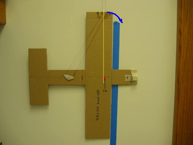
Pictures.. the universal language.

Are you talking about the torque trying to rotate the model in the direction of the blue arrow?

Lou Crane's post 30 just about covers it.

Igor Burger · Nov 30, 2004 03:56 PM

#33 source
No, just opposite, but does not matter, there are always couples. There is always one opposite force. Think about your model without bellcrank. If pivot is in CG then your yellow line goes by lines via CG OK?

If you move pivot back (still no weight) like on your pictures, the lines goes back to pivot, but your yellow lines go still via CG. I think still OK.

But if your BC has some weight, and pivot is in that back position like on pictures, then its weight acts on lines. That force has two components. The weight – acting to lines at begin of yellow line oriented vertically (so not changing anything) and another component perpendicular to the previous force and trying to straighten lines. That force makes moment (torque) turning your cardboard model left. That moment has value weight of bellcrank x distance from yellow line (now I speak bout stable situation – means already turned model). This moment must be balanced by exactly same moment oriented opposite way which comes from weight of model x distance of its CG from yellow line.

So if we speak about the same distance of the same BC from yellow line, and thus constant value of its moment, we can see that if we change the weight of the model, the only way to keep the same moment of weight of model x distance of its CG from yellow line is to change that distance and thus also angle. So as you can see the angle depends on the weight of the model.

BTW did you recognized that weight of hanging bellcrank x distance from yellow line is exactly the same contribution of moment like fixed bellcrank on model … It is also weight of bellcrank x distance from yellow line.

Ted Fancher · Nov 30, 2004 12:42 PM

#28 source
LAST EDITED ON Nov-30-04 AT 12:44 PM (CST)
 
I Really have to apologize to Igor.

I have great respect for his knowledge and talents as a pilot and I'd love to respond directly to his input. Unfortunately, I am simply not able to completely understand the concepts he is attempting to convey in what is obviously a second language. This is clearly my shortcoming rather than his for if I tried to write in his native tongue it would be total gibberish.

One of his posts, I believe, addressed the relationship between tension, CG, Bellcrank position and line drag.

My response would be that the line tension is the result of the force between the tethered point, the pilot's hand, and the center of gravity of the aircraft. This force would be a straight line between the two points.

The drag of the control lines is an aerodynamic force acting opposite the direction of the aircraft's flight path (yes, and a tiny bit "down" thanks to gravity and/or acceleration induced gravity forces). As we all know, the drag causes the lines to bow in what Wild Bill described as a "catenary" arc, such that more bow is evidenced at points farther from the handle as airspeed and thus drag increases due to the rotational velocities.

The location of our leadouts is simply the recognition that this drag exists and that, to keep the aircraft aligned longitudinally "as desired", they must exit the point of tether (the leadout guide) in a location that respects both the fore and aft thrust/drag vector and the in/out tension of the centrifugal force vector.

Is this responsive to your question, Igor?

Ted Fancher

Igor Burger · Nov 30, 2004 04:39 PM

#34 source
LAST EDITED ON Nov-30-04 AT 04:40 PM (CST)
 
>>>I have great respect for his knowledge and talents as a pilot and I'd love to respond directly to his input. Unfortunately, I am simply not able to completely understand the concepts he is attempting to convey in what is obviously a second language. This is clearly my shortcoming rather than his for if I tried to write in his native tongue it would be total gibberish. <<<

Thanx Ted, I knew you are gentleman. But you really not need to write so many letters to tell me about my pure English … trying to improve, but I see without too much success

But to your post. I do not know if I understand EXACTLY what you mean so first I will comment my understanding:

>>>The drag of the control lines is an aerodynamic force acting opposite the direction of the aircraft's flight path<<<

Yes, that is in our case constant force as we are in constant speed flight. OK.

>>>As we all know, the drag causes the lines to bow in what Wild Bill described as a "catenary" arc, such that more bow is evidenced at points farther from the handle as airspeed and thus drag increases due to the rotational velocities.<<<

And I will add that its shape depends on drag of lines and line tension straightening them. OK.

>>>The location of our leadouts is simply the recognition that this drag exists and that, to keep the aircraft aligned longitudinally "as desired", they must exit the point of tether (the leadout guide) in a location that respects both the fore and aft thrust/drag vector and the in/out tension of the centrifugal force vector. <<<

So it means you do not take the aerodynamic forces to the equation. OK. Let’s assume for simplicity that we speak abbot perfectly tangent fuselage and pivot in CG. That will make it simple.

It means you know the shape of lines from drag and line tension equal to centrifugal force in level fliht. We can find the point where lines cut tip of wing. If we put leadouts to this point, then we have no friction in lines, no real force in tip, no yawing and thus stable situation. OK.

But now what happens if you fly overhead. The line drag is still the same. The centrifugal force is still the same. But line tension is less gravity. Therefore the lines are more curved and thus the “proper” position of leadouts are not proper anymore. Lines will push tip aft and thus nose inward.

You know what I mean? We cannot fly such model. That nose in yaw will make line tension even smaller, and it will make force even worse. All that is happening because CG is longitudinally front of leadouts – here I mean in-flight position. Variation in line tension makes yaw.

The solution I wrote is simple. Let’s assume we have rudder with small offset out. I realitywe have it – even straight rudder makes that effect because of circular flow. Otherwise the model is exactly as before. That rudder will yaw the fuselage little out. Lines will be overhanged little bit (means pushing nose in – just against the rudder, but rudder is winning little bit). Model is little bit yawed out.

Now let’s go overhead. The line tension goes down and more curved lines tend to push the tip back, but here we have that another force of rudder (which remains constant as the speed is constant) winning over lover tension of lines and thus compensating drag and curved lines.

And I say that this balance is achieved if CG is in flight aligned with line handle – leadouts. Or by other words if moment from line drag at tip is equal to moment of rudder.

Ted Fancher · Dec 01, 2004 02:22 PM

#41 source
>>>>I have great respect for his knowledge and talents as a pilot and I'd love to respond directly to his input. Unfortunately, I am simply not able to completely understand the concepts he is attempting to convey in what is obviously a second language. This is clearly my shortcoming rather than his for if I tried to write in his native tongue it would be total gibberish. <<<
>
>Thanx Ted, I knew you are gentleman. But you really not need
>to write so many letters to tell me about my pure English
> … trying to improve, but I see without too much success
>
>
>But to your post. I do not know if I understand EXACTLY what
>you mean so first I will comment my understanding:
>
>>>>The drag of the control lines is an aerodynamic force acting opposite the direction of the aircraft's flight path<<<
>
>Yes, that is in our case constant force as we are in
>constant speed flight. OK.
>
>>>>As we all know, the drag causes the lines to bow in what Wild Bill described as a "catenary" arc, such that more bow is evidenced at points farther from the handle as airspeed and thus drag increases due to the rotational velocities.<<<
>
>And I will add that its shape depends on drag of lines and
>line tension straightening them. OK.
>
>>>>The location of our leadouts is simply the recognition that this drag exists and that, to keep the aircraft aligned longitudinally "as desired", they must exit the point of tether (the leadout guide) in a location that respects both the fore and aft thrust/drag vector and the in/out tension of the centrifugal force vector. <<<
>
>So it means you do not take the aerodynamic forces to the
>equation. OK. Let’s assume for simplicity that we speak
>abbot perfectly tangent fuselage and pivot in CG. That will
>make it simple.
>
>It means you know the shape of lines from drag and line
>tension equal to centrifugal force in level fliht. We can
>find the point where lines cut tip of wing. If we put
>leadouts to this point, then we have no friction in lines,
>no real force in tip, no yawing and thus stable situation.
>OK.
>
>But now what happens if you fly overhead. The line drag is
>still the same. The centrifugal force is still the same. But
>line tension is less gravity. Therefore the lines are more
>curved and thus the “proper” position of leadouts are not
>proper anymore. Lines will push tip aft and thus nose
>inward.
>
>You know what I mean? We cannot fly such model. That nose in
>yaw will make line tension even smaller, and it will make
>force even worse. All that is happening because CG is
>longitudinally front of leadouts – here I mean in-flight
>position. Variation in line tension makes yaw.
>
>The solution I wrote is simple. Let’s assume we have rudder
>with small offset out. I realitywe have it – even straight
>rudder makes that effect because of circular flow. Otherwise
>the model is exactly as before. That rudder will yaw the
>fuselage little out. Lines will be overhanged little bit
>(means pushing nose in – just against the rudder, but rudder
>is winning little bit). Model is little bit yawed out.
>
>Now let’s go overhead. The line tension goes down and more
>curved lines tend to push the tip back, but here we have
>that another force of rudder (which remains constant as the
>speed is constant) winning over lover tension of lines and
>thus compensating drag and curved lines.
>
>And I say that this balance is achieved if CG is in flight
>aligned with line handle – leadouts. Or by other words if
>moment from line drag at tip is equal to moment of rudder.
>
>

Thanks, Igor. I appreciate your second effort and, frankly, I think we are pretty much in agreement on the issues.

I have several times over the course of way too many long winded discussions of stunt model design and trim discussed a pragamatic approach to trimming which essentially duplicates your theortical approach.

In my exlanation I encourage pilots to monitor the relationship of the inboard and outboard wheels in level flight on calm days to get a good approximation of the validity of their leadout location. I've used words similar to "you should see some of the outboard wheel aft of the inboard one, maybe a third to a half a wheel".

This relationship of the wheels to one another (assuming they are actually aligned with one another statically...not always true) is a pretty accurate depiction of the summation of forces, aerodynamic and centrifugal/centripetal, acting on the airplane.

It also agrees closely with your description of the need for a modest amount of longitudinal offset from tangent in steady state flight.

Does that sound to you like we are in basic agreement?

Ted Fancher

Igor Burger · Dec 01, 2004 03:57 PM

#43 source
Are those pictures good answer?

... there are many such pictures from WC and Nats and yaw angle is relatively consistent.

Brett Buck · Dec 01, 2004 05:06 PM

#45 source
>Are those pictures good answer?
>
>... there are many such pictures from WC and Nats and yaw
>angle is relatively consistent.

I've got a lot of pictures like that from the Team Trials, and it's *highly* illuminating. I don't care to start any arguments by noting how others airplanes might look, but they certainly were not all the same! But you can take a ruler, project the flap hinge line and it hits me in the forehead. It wouldn't DARE do otherwise!

Brett

Igor Burger · Dec 01, 2004 05:28 PM

#47 source
>>>they certainly were not all the same!<<<
And my question is how and why, that was the reason for that other thread.

>>>But you can take a ruler, project the flap hinge line and it hits me in the forehead.<<<
And that is exactly what I would like to do. Unfortunately we do not have flyable conditions now, I can not make pictures, so if you have picture and data of such model (LO position and CG position) then we can do it. We will see if CG is at LO and if not then how much and to which directon. That is the question. The yaw itself does not mean anything. So may be Ted can start if he wknows data ... do you Ted?

That model on picture is not my and I am not absolutely sure if my calculator shows initial data or data after trimming. I had only one day to trimm that model and to learn it to fly.

Brett Buck · Dec 01, 2004 08:56 PM

#49 source
>>>>they certainly were not all the same!<<<
>And my question is how and why, that was the reason for that
>other thread.
>
>>>>But you can take a ruler, project the flap hinge line and it hits me in the forehead.<<<
>And that is exactly what I would like to do. Unfortunately
>we do not have flyable conditions now, I can not make
>pictures, so if you have picture and data of such model (LO
>position and CG position) then we can do it. We will see if
>CG is at LO and if not then how much and to which directon.
>That is the question. The yaw itself does not mean anything.

I know what you are getting at (that the transient condition is what you are interested in), but I couldn't disagree more. See my response to Lou above. I think the only way you can get no transient *at all* would be with the yaw angle = 0. Of course there are other thing's preventing it. But I think it's what we call a "necessary, but not sufficient" condition.

I might note that Ted's airplane, if not aiming the hinge line at his forehead, is at most aiming it at his left ear. I saw *plenty* of airplanes at the Team Trials that pretty much aimed the inboard LE at the pilot - and that's a BIG angle. Some of the other stuff you could see was pretty amazing, too.

Also note the wheels are very close to lined up, (about half a wheel). Of course, without knowing the wind direction, it's hard to tell if it was affected by crosswinds.

Brett

Igor Burger · Dec 02, 2004 05:48 AM

#50 source
LAST EDITED ON Dec-02-04 AT 06:00 AM (CST)
 
Brett, I do not speak about absolute yaw. I am speaking about in-flight relation of leadouts and CG. That yaw, which I pointed up, is result of my theory that trimmed model has its CG aligned on one line handle – leadouts – CG. And since we put LO little aft of CG on TANGENT position of fuselage and in-flight position of fuselage is little out, the CG after all IS aligned as I wrote.

------------------------------------

Anyway …

>>>See my response to Lou above.<<<

I do not see any post above … I think you mean your post #13 below yes?

OK, I replayed it, may be not so clear. Now I will write how I see it. May be in too trivial steps, but at least no one will misinterpret what I mean (including my own mistakes ).

So you say:

>>>I think the only way you can get no transient *at all* would be with the yaw angle = 0.<<<

I do not think so. It looks cardboard models are successful here so follow me please. Imagine a horizontally oriented cardboard circle. You can pitch it up in any direction. There is no clear X and Y axis. The only what matters is, where you apply forces to pitch it.
It means you can draw a model in any direction to that circle and you can still pitch it the same way. Also with fuselage at 45 degrees. You can also cut it out by outlines, put x and y axis and you can still pitch it at any direction, independently where they are. You can also do it on real model if you take it by LE on left tip and TE on right tip. It will do very clean 90 deg corner without any roll … and yaw is still constant before, after and also inside the turn.

The only what is necessary is properly apply forces.
So you are right if you wrote that there is a lift vector, mass inertia and I add also tail lift vector which needs to be properly balanced to achieve that situation. What I do not understand is, why you this it is not possible if model has some yaw angle. At least if I can say for myself, I do it while trimming. I play with tip weight (Ywise moving of CG), outboard flap (temporary Ywise moving of wing CP), rudder offset ywise moving of tail CP. Do you think it is not enough? Where? Why? When? Did I miss someting?

Thinking that model is symmetric, that ACs are aligned, that CG is somewhere in middle, that elevator is pretty aft of AC of wing is only illusion, we know we are on circular path and everything is little bit shifted somewhere, so at trimming we must solve this misaligment anyway, and little yaw can be well hidden in the result.

And one note on top here if we put CG very close to CP of wing like we do it now - at 25% of MAC, then we will minimize lot of those problems with aligning because lift vector and mass inertia are collocated.

In previouse posts I found a problem with “proper” yaw angle, but that can be also solved for example by another trimming tool allowing move stab right and left and thus move AC of tail independently on fuselage angle, but this can be solved by proper design before building, and I do not think such a disproportion is too critical.

But again, this is NOT my primary point. My primary point is, if that yaw force caused by line drag is balanced by CG centrifugal force front of INFLIGHT LO position, or by aerodynamic outboard force on fuselage. To know this, it needs to inspect in-flight yaw, position of CG and position of leadouts. My point is that this theory of line tension equal to CF force only, needs to have CG in-flight aligned with LO and my question is, if we really do it so – or if we have some feedback to yaw regarding line tension.

---------------------------

And on end to those pictures:

>>>I saw *plenty* of airplanes at the Team Trials<<<
>>>wheels are very close to lined up, (about half a wheel)<<<
>>>without knowing the wind direction, it's hard to tell if it was affected by crosswinds. <<<

OK fine, so put here some pictures where you know it was in calm, where you know CG position and where is clear what is the yaw.
I asked Ted for details, because I think that picture was done at WC final flights at relatively low wind, we see the angle and if he can provide LO and CG position, then we can start serious speaking.
In any case my optimally trimmed models always tend to look out. In level and also overhead. I cannot say more for now, but I will definitely measure this thing in spring.

BTW those pictures are by Will Hubin – so Will if you read this, thanx for the CD.

godzilla · Dec 01, 2004 07:47 PM

#48 source

>In other words, the airplane always wants to yaw outboard
>because of rudder/engine offset but is constrained from
>doing so by the leadout guide and CG relationship. The
>likely result is that when your leadout guide is in place
>the aerodynamic attempts to yaw the airplane are still there
>and are forcing the inboard wing "forward" of where it would
>naturally fall.
>
>This is a classic case of the sort Brett has addressed where
>aerodynamic forces and the leadout position work against one
>another thus creating a ship that will alter its yaw
>condition during accelerated conditions. This might well be
>the source of what Jim has described as "walking" during
>maneuvers, etc.

I know that Ted has said he will not respond to my comments, but I hope in this case, he might make an exception.

This is what I have seen:

In the extreme condition, it is simply impossible to corner the airplane hard. The airplane seems to expend a tremendous amount of energy in a hard corner. If the leadouts are exceptionally misaligned, the forces used to "flip" the tail are expended in some other fashion, in the airplane will "soften" through the corner and not "flip". In this manner it is imperative that the leadouts match the yaw angle "neutral" to maintain the same energy level through the corner.

The City Smasher

Brett Buck · Nov 29, 2004 10:23 PM

#11 source
>I dunno, I had the lost-the-leadoutguide-bolt thing happen.
>The leadouts promptly migrated to the rear of the slot and
>stayed there for the rest of the flight.

Must have had some outboard yaw torque.

Brett

Igor Burger · Nov 30, 2004 03:41 AM

#17 source
You have, but I the secret is in my post to Ted above and it has only little to do with aerodynamic forces.

Lou_Crane · Nov 29, 2004 11:20 AM

#3 source
Ted,

Nicely put!

Is there any objective reason to see "fuselage centerline tangent at CG to flight path circle," as optimum? (Not sniping, just would like to hear one or more. It could be one of the intuitive traditions, some of which have often proven not quite correct.)

Should we go for a 'resolved' set of forces to achieve the optimum 'level cruising flight trim'? By this, I ask if we should aim for force and load vectors which are not lined up through a defined point, such as CG, but which have a net effect cancelling out deviations for that condition? (What happens when the high-g gyrations start??)

Or should we try to pass as many of the forces through the *dynamic* CG (in flight)? If we can account for all the significant factors, that arrangement should hold true for more variations of velocity and g-load, shouldn't it? It wouldn't cover them all, of course, as the torque, gyro, and possibly other strong force factors DO cause roll and yaw twitches -- which change the presentation of the model to the air it moves through.

I value any comments you'd care to make, as you are one of the relatively few who not only has a grasp of such things, but who flies well and often enough to observe analytically your model in flight.

Best through the remaining Holidays to you and Shareen!

\BEST\LOU

Brett Buck · Nov 29, 2004 11:09 PM

#13 source

>Is there any objective reason to see "fuselage centerline
>tangent at CG to flight path circle," as optimum? (Not
>sniping, just would like to hear one or more. It could be
>one of the intuitive traditions, some of which have often
>proven not quite correct.)

I think so. The problem with anything else is that whatever else you do results in yaw motion (and thus roll motion). Not to mention that the kinematics of rapidly pitching mean that the airplane has to either rotate about the unperturbed Y axis (and thus end up pointing the lift vector in at you), or the airplane has to both pitch and yaw simultaneously to keep the Y-axis at some off angle to the circle. Or through some indeterminate means, rotate around the "circle Y" axis, meaning some odd axis that couldn't reasonably be expected to be a principle axis, and thus get some products of inertia.

To visualize this, assume you are flying yawed out. Define a "circle frame" that is +X along the tangent/velocity vector, +Y directly away from the pilot, and +Z to make it an orthogonal set. The Y of the body frame, instead of being pointed directly away from you, also has a component in -X in the circle frame. Then rotate the airplane 90 degrees around the +Y body axis. +X body is now vertical, +Y is unchanged, and +Z is mostly horizontal, but has a component along Y in the circle frame. Unfortunately, there's a lift vector in -Z body, and it has a component aimed towards you. To correct that, the airplane would have had to do a roll/yaw maneuver, too. Meaning, since it has a non-zero inertia you have to provide some torque to start it, and to stop it. I think this inevitably results in a perturbation.

The only way it could conceivably work with a large yaw angle is if you made the Y body principle axis to line up with Y circle axis, and that means putting a large dynamic imbalance that would change every time you changed the yaw angle. OR (and here's completion of the logic), you could fly with the Y principle axis parallel to the Y circle axes BY FLYING WITH THE AIRPLANE TANGENT TO THE CIRCLE IN THE FIRST PLACE - in which case you don't have to do anything but pitch around, the only net torque is there to change the angular momentum vector from vertical to horizontal.

The airplane want to pitch around it's own principle pitch axis, and anything else is going to either require a strange balancing act between the torque from the off-diagonal terms in the inertia tensor)and the aerodynamics, or (more likely) will result in some pretty wild gyrations. That's pretty much what seems to happen in practice, too, except in some fairly strange situations.

I'll make some illustrations when I get a chance, but I think it's pretty clear even without the picture. I can't draw well enough to make really good illustrations - which is also one reason why I don't to more articles.

That's my grasp of the situation, and I think it's probably right as far as it goes. Technically, what you really want is the +Y principle axis along a radial line of the circle. I am making the assumption that the airplane's inertia tensor has the principle axes lined up with the geometric Y axis. If not, then you might end up with it flying non-tangent.

I assume the other types of perturbation (yaw aerodynamics VS leadout torque, tip weight, thrust vector not aligned with CG) are obvious, but I don't think that you can do a lot better than tangent. Those kinematics effects are very real.


Brett

Lou_Crane · Nov 30, 2004 02:02 AM

#14 source
LAST EDITED ON Nov-30-04 AT 02:09 AM (CST)
 
Brett,

Thanks! The only difficulty I had with your comments was that not a 'current member of the fraternity' I'd come to think side view as the X-Y Plane, with Z spanwise. Sort of like trying to think metrics when raised on Imperial/SAE units... No biggie.

I've been trying to group the lines of action centered as nearly as possible AT the CG for many years. Models fly nicely, but I still would need to practice more than I care to, to develop the 'eye' and 'feel' to evaluate what I've missed. (Sure to be something...)

\BEST\LOU

Brett Buck · Nov 30, 2004 10:19 AM

#23 source

>Thanks! The only difficulty I had with your comments was
>that not a 'current member of the fraternity' I'd come to
>think side view as the X-Y Plane, with Z spanwise. Sort of
>like trying to think metrics when raised on Imperial/SAE
>units... No biggie.
>

Well, even the Wright brothers assumed the same axis system - and that was because it was well-established even before then!

Same thing on spacecraft - the circle frame corresponds to the "orbit frame".

Brett

Igor Burger · Nov 30, 2004 04:00 AM

#18 source
>>>The airplane want to pitch around it's own principle pitch axis<<<
Question is, what is that "it's own principle pitch axis"

We can easily fly sidewise, because:
>>>balancing act between the torque from the off-diagonal terms in the inertia tensor)and the aerodynamics<<<

by other words model can have natural rolling programmed to natural pitching, and we do it - we are trying to find proper Ac to AC position of tail and proper outboard flap size to achieve it.

so if done well, I do not think it is:
>>>pretty wild gyrations<<<

I think there is a way how to properly trim both - natural yaw by rudder and to that yaw fix the natural roll as response to pitching by Ac to AC or outboard flap

And I think that is what we do right now, I inspected photos from Nats and WC. There plenty of shots showing model in level flight together with pilot. It not only shows it IS outboard, it shows also very consistent angle at succesfull models. Unfortunately none of them shows CG location so it is difficult to check inflight CG to leadouts position.

Ted Fancher · Nov 30, 2004 09:13 AM

#20 source
As everyone knows, I have the greatest respect for Brett's wisdom and interpretation of this stuff.

However, for us mathematically disadvantaged individuals, I wish her would refer to roll, pitch and yaw axes. It would make interpeting his post a lot easier. I'm sure there is a good reason for his choice of nomenclature but I get all tangled up alphabetically.

Please be gentle.

Ted

Brett Buck · Nov 30, 2004 10:13 AM

#22 source
LAST EDITED ON Nov-30-04 AT 10:23 AM (CST)
 
>As everyone knows, I have the greatest respect for Brett's
>wisdom and interpretation of this stuff.
>
>However, for us mathematically disadvantaged individuals, I
>wish her would refer to roll, pitch and yaw axes. It would
>make interpeting his post a lot easier. I'm sure there is a
>good reason for his choice of nomenclature but I get all
>tangled up alphabetically.
>
>Please be gentle.


I know you already know this, but for the benefit of newbies:
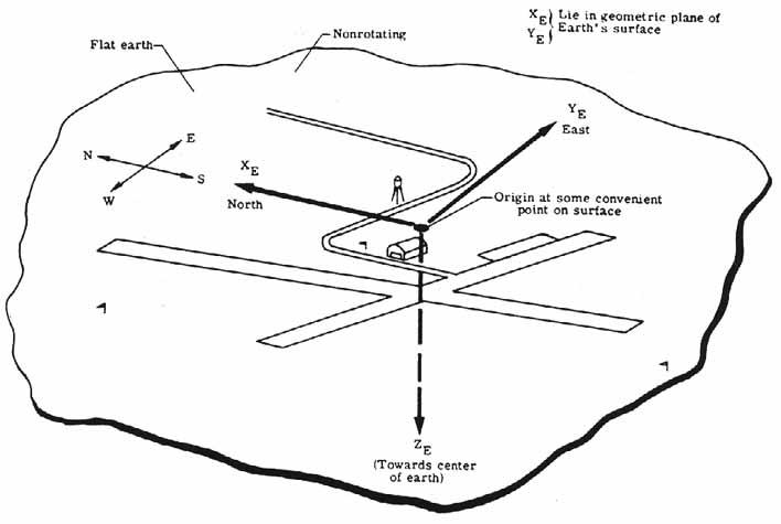
X=roll axis= longitudinal axis Idown center of fuse), positive = direction of flight
Y=pitch axis = horizontal axis (flying level) (parallel to span), positive = out the right wing (so that a positive pitch is nose-up)
Z = yaw axis = vertical axis, (flying level), positive = down (nose right = positive)

The problem with this is that to really explain what we were talking about, you need to define TWO reference frames - The "circle" frame, and the "body" frame. Roll, pitch, and yaw are understandable enough when applied to the body, but it's quite a stretch to relate them to the "circle" frame. They are coincident when flying level and tangent, but as soon as you start maneuvering, they may be different.

The "circle" frame is defined as:

X= tangent line to circle, always in direction of velocity vector.
Y= radial line from pilot to aircraft CG, positive away from you
Z=perpendicular to X and Y

Roll, pitch, and yaw are the angles between the circle frame and the body frame, and if they are 0, X body = X circle. Without some reference frame, the idea of roll, pitch, yaw are undefined. For C/L models, to first approximation, there's always a rate around Z circle corresponding to the rotation of flying on a sphere.

Brett

p.s. Since it willl take a while for me to get around to it, here are some good sketches that describe what I am talking about in terms of axes definitions:
http://history.nasa.gov/SP-367/appendc.htm
The "wind" frame is the same as the "circle" frame, with the modification that there is always a constant rate around Z of the wind frame resulting from the constraint of the lines.

Dick Fowler · Dec 01, 2004 01:32 PM

#40 source
LAST EDITED ON Dec-01-04 AT 05:59 PM (CST)
 
Brett help! .... I'm confused.


As seen by Sourdough

[photo not recovered: 41ae2270651bd025.jpg]

As seen by me ( Ohio)


Relatively speaking, what's happening?

Chuck Smith · Nov 30, 2004 01:41 PM

#31 source
Brett, I agree with what you say. It seems to me, that for static stability around the Z axis, we could take the sums of the moment coefficients traditionally used for a free flying aircraft and add one for the leadout force which would be a simple cross product of the geometry, line pull and rearange and solve for the zero trim position of the leadouts (Z axis). This would be slightly complicated by the two superimposed catenary curves for the leadouts which would be speed dependent. Which would prove interesting if we look at the angular momentum associated with flying level. The lines are what provide the moment to keep the airframe rotation around the Z axis, when you think about it. So we can surmise since the model is in a constant state of rotation in level flight there is a balancing moment. Dynamic stability due to roll and yaw moments could also be determined using the tension and geometry if you think about it. We could define moment coefficients such as resultants of the line tension WRT the fixed body axis, but the problem is they are not aerodynamic forces, but mechanical. No problem, we just treat them like vectored thrust only we mounted the nozzle on the wingtip, or even use a version of an RCS analysis. The problem is sovleable, but gathering all the data would mean lots of wind tunnel time to get all the aerodynamic coefficents of the model, and would require the use of a powered model too. Blech!

The problem I always run into with this is should I consider the plane as free flying with lines attached, or should they be added to the tensor of the airframe - which is messy because it removes a plane of symmetry (XZ) and messes up the equations?

Then I get into the whole situation that the axis of rotation, aka the pilot, is not fixed, and the relationship of the control handle to the pilot isn't fixed either. Yuck!

The more I think about it, the more I guess I'll just go with what works. A time-tested way to approach a problem in aircraft design.

Brett Buck · Dec 01, 2004 12:35 AM

#36 source
>Brett, I agree with what you say. It seems to me, that for
>static stability around the Z axis, we could take the sums
>of the moment coefficients traditionally used for a free
>flying aircraft and add one for the leadout force which
>would be a simple cross product of the geometry, line pull
>and rearange and solve for the zero trim position of the
>leadouts (Z axis).

Sure, that all sounds right to me - although I don't see how it directly relates to the kinematics effect I was discussing. All I was trying to do was anwser the question Lou asked - i.e. why can't you use static trim angles other than 0.

Of course, for a full description of the motion, you need to take in all the factors. Static stability is not all you need. If the moment coefficients are accurately scaled (i.e. real values instead of relative values) you could use it to calculate or estimate things like the torque vs. yaw angle, stuff like that, and that would be quite useful.

The line dynamics are a neat little problem. To add it to the other torque (and forces) is trivial. Modeling the motion is a little bit more complicated. I'm not sure there is a closed-from solution. And I've never been able to get my finite-element model to work properly. It's a little bit more complex than the classic "loaded string".

>This would be slightly complicated by the
>two superimposed catenary curves for the leadouts which
>would be speed dependent. Which would prove interesting if
>we look at the angular momentum associated with flying
>level. The lines are what provide the moment to keep the
>airframe rotation around the Z axis, when you think about
>it. So we can surmise since the model is in a constant state
>of rotation in level flight there is a balancing moment.
>Dynamic stability due to roll and yaw moments could also be
>determined using the tension and geometry if you think about
>it. We could define moment coefficients such as resultants
>of the line tension WRT the fixed body axis, but the problem
>is they are not aerodynamic forces, but mechanical. No
>problem, we just treat them like vectored thrust only we
>mounted the nozzle on the wingtip, or even use a version of
>an RCS analysis. The problem is sovleable, but gathering all
>the data would mean lots of wind tunnel time to get all the
>aerodynamic coefficents of the model, and would require the
>use of a powered model too. Blech

I don't pretend to know all the answers to this problem. I think I know just enough about it to know the right questions. That's not bad, actually.

I can't articulate the entire thing, but I can visualize just well enough make use of it in practice to some extent.

>
>The problem I always run into with this is should I consider
>the plane as free flying with lines attached, or should they
>be added to the tensor of the airframe - which is messy
>because it removes a plane of symmetry (XZ) and messes up
>the equations?


It's worse than that. The classic way of approaching this sort of is to make a finite element model of the entire system, treating the airplane as a rigid item (which is probably good enough for this part of the problem). Of course I can't get my finite-element model of the lines right, so not much point in trying to hook an airplane up to it.


>Then I get into the whole situation that the axis of
>rotation, aka the pilot, is not fixed, and the relationship
>of the control handle to the pilot isn't fixed either. Yuck!
>
>The more I think about it, the more I guess I'll just go
>with what works. A time-tested way to approach a problem in
>aircraft design.

Having a concept of the principles involved is certainly more efficient than just trying stuff at random, so partial understanding is very useful. That's as far as I ever expect to get!

Brett

Chuck Smith · Dec 01, 2004 07:45 AM

#37 source
Yep Brett. I think it would make a lot more sense if we each had a beer and there was table dancer.

The more I think about it, I think line tension is more an effect of conservation on angular momentum and aero-effects are secondary. Heck, even a bucket full of water swinging on the end of a rope has a drag coefficent and gravity acting on it, but it's the angular momentum that keeps the water in the bucket. And I don't even need to compute the Euler angles to describe it.

That's it! From now on I'll model the plane as the bucket and the fuel as the water.

Chuck Smith · Dec 01, 2004 08:46 AM

#38 source
> The line dynamics are a neat little problem. To add it to
>the other torque (and forces) is trivial. Modeling the
>motion is a little bit more complicated. I'm not sure there
>is a closed-from solution. And I've never been able to get
>my finite-element model to work properly. It's a little bit
>more complex than the classic "loaded string".

Man, how true. When you consider the lines have mass and angular momentum the whole thing snowballs. Whenever the inertia tensor becomes a function of the conditions and not a constant, it's a mess.

Do you account for the lines' linear mass density in your model? If so, my hat's off to you.

Igor Burger · Nov 29, 2004 03:14 PM

#6 source
Ted, that is exactly what I wanted to know in topic "Leadouts position".

You have good question:
>>>determine the aerodynamically proper position for leadouts<<<

I say, yes we definitely can, IF we can say what we expect. How that model should fly. What is that most important property?

And here is I think answer to your question:
>>>Isn't that pretty much what Brett has been trying hard to describe for us for the last several years?<<<
Depends what we want – is it constant line tension? No problem we can force to point the nose in relation to the line tension out of the circle overhead and to the center in level flight. We can easily do it by some clever device measuring line tension, but same way we can match leadouts with CG – the way that lover line tension will allow CG to yaw fuselage out. It is very simple – just move leadouts more front. But is yawed nose overhead really wanted? I think no. Because of drag, because of misaligned wing and tail, because of rich engine ….
So it looks that way which Brett suggest is proper. Means limit line tension to centrifugal force, limit all unwanted yaw variation and response to strong inputs in corners. (sorry Brett that I packed it to one line only )

But here comes the trouble which I wanted open in that my topic. And that is all concentrated in question written by Lou:
>>>Is there any objective reason to see "fuselage centerline tangent at CG to flight path circle," as optimum?<<<

And I think that is the point. Because I not only think that the answer is NOT. I also think that Brett’s suggestion is in contradiction with perfectly tangent flight.

Reasons are written in that my topic, so I will now try to collect all to following hypothesis:

1/ Beside that static point of view that there is line drag concentrated in tip and CG little front of leadouts counterbalancing that drag, we have also aerodynamic forces in the same equation.

2/ If we really want limit yaw variation regarding centrifugal force and impulses from controlling to minimum, then GC must be IN FLIFGT aligned with leadouts. That is also one of Brett’s trimming operations – “do a corner and put leadouts to place where are yaws smallest” am I right?

3/ If The CG is aligned with leadouts, the CG cannot counterbalance line drag. Therefore (I am sorry TED) we must count with aerodynamic forces keeping straight fuselage to continue in straight path thus yawing nose out of the circle. And even more – I say that that yaw moment is equal to line drag. We know it is here, we know how to calculate it, we can find proper leadout position.

(I must wrote one note here – I REALLY REALLY do not speak about mass inertia continuing in unaccelerated motion – I am speaking that flat straight body in motion in fluid stream makes resistance to rotating – it happens because any rotation of moving body makes lift and that is force)

4/ fuselage makes also lift on its side. Not much but makes. If the fuselage is perfectly tangent the lift is oriented toward the center of circle, thus against us. That is also because of circular flow around straight body. I did calculation and found that no lift AoA of typical fuselage at typical circle diameter of large model is ~1.5 degrees. We can easily find that also rudder is at zero AoA if fuselage is at that AoA (I mean out of the circle). So if we want limit line tension to centrifugal force we must keep constant yaw those 1.5 deg.

5/ so conclusion is: we will keep leadouts aligned with CG, we will keep fuselage at zero lift AoA 1.5 deg and to reach all of that we need only proper rudder offset (typically close to 0). Pretty easy to trim and pretty easy to calculate. That would be model with no yawing depending on line tension – depending on elevation or control impulses.

6/ Here is little trouble, because Brett told us something else about the rudder. He recommends adjusting rudder to minimize differences in roll between low and hard G’s. That is what comes from swinging lines and excessive tip weight in tight corners and misalignment of wing AC with tail AC. So that is what I already wrote in that previous thread to Godzilla. Here we have two different properties trimmed by one tool and that makes problem. Fortunately we have another tool and that is asymmetric wing planform and flaps. So we can use rudder/leadouts for line tension. And small flap panel to roll trimming.

So that is how I see it. And what we do now? We do usual model which worked for years wit minor modifications, we expect fuselage tangent to circle and we use line drag against CG centrifugal force on base of calculation in hope that it will balance the drag. But what is reality? Model looking out if the circle and lines sawing leadout guide.

Lou_Crane · Nov 30, 2004 01:28 PM

#30 source
LAST EDITED ON Dec-01-04 AT 10:32 AM (CST)
 
(Edit: 1 Dec 04 - I know, I know! I didn't use the 2 Kg value in the translation to US standard units. This edit corrects that. I hope...)

Igor,

I always enjoy your thoughts!

The fore and aft forces applied to leadout guides to resolve a misalignment when pull force's line of action aims through the guides and MISSES the CG, are small. I consider the lines limp, carrying their load in their length axes, and of limited ability to exert force across their lengths.

Say we have a 2 Kg model "pulling" 3 g (CF) with a 70 cm inboard span from spanwise CG to guides. I'm still not sure of my metric terms, please bear with me and correct as needed?

If the lines come to the guides at a trail angle of 5º, for the leadouts to float without touching the guides, the guides need to be aft from the imaginary line from center of flight circle to CG.

To fly tangent(at CG), LO(aft)= (70 cm)* (Sin(5º), or 0.087) = 6.1 cm

If, instead, the lines enter the wing 10 cm aft, unless something else acts, the inboard wing tip will tend to yaw forward about 4 cm to align pull with the CG, correct?

If other factors, like fin, deliberate or automatic offsets (thrust and straight fuselage), hold it tangent, or where we trim the model to fly, what then? Find the force at the guides this way?

Misalignment torque from force passing ~4 cm (.04 m) from CG:
6 Kg * .04 m = 0.24 Kg m (terms?)

Counter-torque at tip guides 70 cm (0.7 m)from CG:
F * 0.7 m = 0.24 Kg m
F = .024 Kg m / 0.7 m = 0.034 Kg

(Edited 1 Dec 04)
The above, translated for traditional USA types: a torque caused by 13.2 lb (158.4 in oz) pull force, passing 1.6" from the CG, makes a yawing torque about the CG of 253.4 in oz. The tip guides. 27.5" inboard of CG. need to 'bear' about 9.2 oz to balance that torque.

The total yaw angle for the extra 4 cm aft guide location would be:

Sin(angle) = dist / inb.length = (4 + 6.1) / 70 = 0.144
Angle = 8.3º

We started with 5º rake angle above. A powerful restoring torque appears with just 3+º yaw added (or subtracted, if yaw was nose-in.)

This long-arm leverage is one of the largest stabilizing forces we use. It is THE largest non-aerodynamic one. It helps steady the model in yaw and roll, in the same way we saw with resolving yaw from pull forces.

Deviations caused by wind, maneuvering loads, torque, gyro precession, pilot error, or whatever, shift the wing slightly, and the pull-force, aimed through the leadout guides, quickly becomes VERY powerful to restore 'trimmed' attitudes.

IMHO, anyway...

\BEST\LOU

Igor Burger · Nov 30, 2004 05:08 PM

#35 source
I see you enjoy metric units. The beauty is that is you work with basic units in equations, you always get proper units without using “magic” constants.

Just one little note – we have different units for mass and different for force (and weight is force). So we never use multiplication 4 cm * 6 Kg. We always use 0.04m x 60N and that gives directly 0.24Nm (approximately).

Lou_Crane · Dec 01, 2004 11:33 AM

#39 source
LAST EDITED ON Dec-01-04 AT 11:47 AM (CST)
 
Igor,

Thanks again for the kind words!

Yes, I am not completely easy using metrics. The Newton, in particular. That factor of 10, that I used incorrectly, just about corrects the difference between the metric unit results and the traditional USA unit results.

Brett is seeking a degree of accuracy beyond what I have found useful. That is excellent, and will almost certainly bring a better final aproach than existing, simpler ways to estimate things.

I think it was J. van Hattum, from Netherlands, who published a fairly simple way to estimate propeller gyroscopic precession. That, too, appeared in an older Aeromodeller Annual. It shows a fairly strong couple tending to influence yaw. (In the spreadsheet I sent you, I use it to estimate leadout fore/aft separation, with UP line forward, to use pull shift to the acting line to oppose the precession couple.) Unless something opposes it, the yaw disturbance looks strong enough to cause a lift variation -- the advancing wing panel lifts/drags more, the retreating panel less.

Peter Soule' published a fairly simple, and very useful, way to estimate the angle along the lines' 'accelerated catenary' where they reach the model's wingtip. With a little empirical adjustment, I use that to design leadout location for original or re-"engineered" models I build. That is also in the spreadhseet I sent you. Soule's equation concerned mainly F2A models (speed - for AMA types) and did not look at the yaw and roll effects of our high-g maneuvering at all heights on the flight hemisphere.

Also not mentioned in this thread is engine torque changes. I may have it wrong, but I see that the model MUST decelerate from cruising conditions, when we start a turn, due to a large increase in induced drag. In 'cruise' the engine torque applied to the model is small, because the prop only adds little thrust to maintain steady airspeed. It is mostly 'coasting' except for that small thrust amount.

Decelerating from induced drag to turn in a maneuver MUST change the prop loading from 'coasting' to loaded more. The load partly shows as increased torque passed into the model. That causes a roll disturbance, always according to direction of prop rotation. The long arm stabilizing effect of leadout placement quickly limits how far the roll tendency goes.

The increased load is what causes the RPM drop that makes tuned pipes work, and probably also causes much of the firing mode switch from 4 to 2 on unpiped engines. Tuned pipe models fly at RPM where the pipe is too high in the 'boost' range to continue to accelerate the model, above the boosted torque maximum. Load pulls RPM down toward maximum boost, and very quickly more torque is there to reduce deceleration from aerodynamic loads. That is as I understand the pipe action...

In another thread, I mentioned that my first concern was the strong forces we CAN identify and estimate. The simple static demonstration that the CG will try to line up with the pull line of action is not so bad -- if we remember to think about the other strong and medium forces that exist when the model flies.

My approach is to try to make sure the strong forces all aim through the CG, or as nearly as possible. Dynamic misalignments can make large torques just as quickly as the model can turn.

If thrust is not aligned spanwise with the CG a couple forms that acts to disturb in yaw.

If the dynamic drag midpoint is not in line with CG in flight, a couple forms that acts in yaw.

The drag midpoint and lift midpoint should be the same, so this also puts more lift to one side of the CG: this couple affects roll.

Even my more crude use of reasonably -- not perfectly -- accurate methods is (was?) an improvement over what was there before. Some VERY lucky practical guesses (like the sizes of early bellcranks and control horns) made CL successful enough that, now, some among us look deeper into what is really going on. Some of us can, and want to, be as accurate as possible. Others accept that it may not be perfect, so long as the models fly as well as, usually better, than the flier.

\BEST\LOU

Igor Burger · Dec 01, 2004 04:14 PM

#44 source
>>>If thrust is not aligned spanwise with the CG a couple forms that acts to disturb in yaw. <<<
Exactly problems like this was reason I started that "leadout position" thread. I think that the theory about CG aligned with leadouts making stable situation independent on CF looks theoreticaly acceptable, but that my original question was if this is really that best position. For example if it is not beter to move CG even more back and let the model be more "positively" sensitive to lower line tension. Especially at situation of total lost of line tension. Isn't it better to live with little yaw out? Could be it was reason why I lost my model in Muncie. Or in this your point - if model does hard maneuver isn't it better to give him little chance to look out ... more drag -> more thrust -> more yaw?

I think I will do some inflight measurement in spring.

Lou_Crane · Dec 02, 2004 10:59 AM

#51 source
Igor,

Yes, I too believe that thrust aimed away from flight circle center is basically good, rather than bad.

When all other trim conditions lose effect, the model is often in a high drag condition. Thrust applied to the model increases to try to meet that drag. If the thrust line is away from tangent direction, it may be the only force left to try to restore taut lines.

The loss of efficiency from structural out-thrust plus straight fuselage automatic out-thrust is small. Automatic out-thrust is often about 2º; adding 3º structural out-thrust makes a total of only 5º.

The trigonometry then is this:

T = total thrust, T(x) is "forward component" and T(y) is "spanwise component"
T(x) = T * Cosine (5º) = 0.996 * T
T(y) = T * Sine (5º) = 0.087 * T

So, we could say that for a loss of 0.4% of "forward" thrust, we get almost 10% (8.7% in this sample) "outward" thrust to help us recover. And we should see similar results if we analyze thrust's line of action past the CG as creating a nose-out torque. (Now, if I didn't screw up naming the Axes, again...<g>)

I am more concerned about the sharp yaw and roll effects of the other strong couples I mentioned.

Discussion of definitions of SI units should not cause hard feelings, by the way. (I hope not.) Brett defined terms in the way they are important for his use in his profession; the definitions you listed are obviously important to you. The descriptons are valid, even if his -or your- choice of words may sound a bit different. I enjoyed an excellent refresher on the topic from both your comments!

\BEST\LOU

Igor Burger · Dec 02, 2004 11:33 AM

#52 source
Lou, sorry for confusion. I did not mean what I wrote. … I mean this part:

>>>Isn't it better to live with little yaw out?<<<

That clearly leads to this understanding:

>>>T(x) = T * Cosine (5º) = 0.996 * T
>>>T(y) = T * Sine (5º) = 0.087 * T

This is true, but not what I mean. I mean DIFFENENCES of that yaw angle as response to the line tension.

By other words as I loose line tension is it any good if model yaws out? For line tension and surviving in critical situations certainly, but isn’t it counterproductive in regular flight – because it also means yawing in maneuvers.

That all depends on LO to CG in flight position. I do not know if I wrote it well now, I think I had to make pictures, but it takes more time … may be on weekend …

Brett Buck · Dec 01, 2004 03:01 PM

#42 source
>I see you enjoy metric units. The beauty is that is you work
>with basic units in equations, you always get proper units
>without using “magic” constants.
>
>Just one little note – we have different units for mass and
>different for force (and weight is force). So we never use
>multiplication 4 cm * 6 Kg. We always use 0.04m x 60N and
>that gives directly 0.24Nm (approximately).

I don't know who "we" is but I (unfortunately) see Kgf and similar things all the time. After the Mars Climate Observer screw-up, a lot of metric zealots started making a lot of jokes - like "Go to NASA, and ask every engineer how much he weighs and if he says XX pounds, fire him!". But I asked them what the right answer was, and *every single one of them* said "XX Kg". So I told then I would fire anyone who answered like that, too - since of course the correct answer is xx newtons.

You just can't argue that metric units are free from "vernacular" uses like Kgf. Once you start doing that, spurious "9.8"'s start sprouting just like spurious "32.174"'s and you right back in the same boat. And I contend it's hardly any easier to remember that a prefix of D means multiply by 10 and d means divide by 10, than it is to remember that there are 12 inches in a foot. So, "no sale" on metric for me. If feet and pounds were good enough to put a man on the moon, they're good enough for anything else.

For the record, fundamental units in either system are:

parameter/english/metric
m (mass)/slugs/Kg
x (distance)/feet/meters
f (force)/pounds/Newtons
p (momentum)/pound-seconds/newton-seconds

I (inertia)/slug-ft^2/kg-m^2
theta (angle)/radians/radians
T (torque)/foot-lbs/newton-meters
h (angular momentum)/foot-lb-seconds/newton-meter-seconds

t (time)/seconds/seconds

14.59 KG = 1 slug
.3048 meters = 1 foot
4.45 Newtons = 1 pound

under Earth's gravity
1 slug weighs 32.174 lbs
1 kg weighs 9.8 newtons

lbs are slug*feet/sec^2
newtons are kg*meters/sec^2

Brett

Igor Burger · Dec 01, 2004 05:16 PM

#46 source
Brett, I see you are little bit sensitive to such words ... sorry for that.

But be sure I am not trying to sale something. Use what you like, I also use inches if I look for props in shop and I do not have any stress with it. I am also not dividing word to fractions. “We who use it” are we who use it, and those others are those who do not. We had enough barriers, walls and separations in past and we do not need others. (“we” here means “we” who are such and not those who are different )

I am not going convince you, however I have some notes to your examples:

The actual metric SI unit system (from French Systeme Intrnational d’unites) covers former MKSA system and extends it to another types of units. If I wrote about “metric” units I related all to SI system, not those “d”s and “D”s which has no real use. (maximally if you ask for apples in shop) … It will also look funny if you write 10 kg like 1Dkg

But I wanted point especially to your conversion between mass and force by gravitational acceleration. Why gravity? Why not air pressure or water density? I really do not know if you are yoking … so sorry if yes. I take it seriously.

It has absolutely no background in unit’s definition. It is property of earth, not unit in SI system. Such relation between units could be typical for your imperial system (I do not know if it is common or not). I do not say it is anything wrong – we (sorry for that again) also know that 10N on earth is ~1kg and that 1m^3 of water is approximately 1000kg (everywhere). We have also defined basic MKSA units on base of material properties like meter on base of wave length of crypton, second on base of wave of cesium, or even really silly definition of kg like mass of piece of metal stored somewhere in Sevres. But REALTIONs to other synthetic units is constant free:

Newton: 1N = 1kg x 1m / s / s
It means if you act by force 1N for period of 1 second, you will get speed 1m/s

No magic constants, no 9.8 coefficients.

And it is not only movement, it is also pressure:

Pascal : 1 Pa = 1N / m^2
(1N on area 1m^2)

energy and power:

Joule : 1J = 1N x 1m
(if you apply that 1 N on distance 1m long, you do 1 Joule)

Watt : 1W = 1J / s
(if you do 1J every second, you have power of 1 W)

If you take Ampere from MKSA you can join that above to electricity:

Volt : 1V = W / A
If you substitute W to m^2 x kg x s ^-2 you have constants free relation of kg to volt

Let’s go to optics:
Dioptry 1 D = 1 / m

Or magnetic induction:

Tesla 1T = kg x m^-2 x A^-1

This is what I mean, not some properties of Earth or Moon. I am sorry that Earth is too little to reach 10 instead of 9.8, but it has nothing to do with metric system.

I am not trying to compare to imperial units, because I have too little experience and I would certainly do similar mistakes. I just wrote that I like that constant free system of definitions, that’s all.

Dick Fowler · Nov 29, 2004 06:04 PM

#7 source
I think we should add to the discussion vertical CG location. The real CG is in three dimensional space not just along the fore and aft axis. It could be above or below the pont that we determine is horizontal CG and shouldn't be thought of as the "sweet spot" that is resting inside the wing on the centerline. This probably accounts for some trim issues that get people head off in all directions. Tip weights, trim tabs, etc. Sometimes the cure is a well placed set of wheels.

EricV · Nov 29, 2004 08:15 PM

#9 source
LAST EDITED ON Nov-29-04 AT 08:19 PM (CST)
 
I'm going to try to throw in 2 cents here, because that is only how deep my pockets go on this engineering stuff...But here goes...

The pragmatist in me has a hard time believing there are any true "Ideals" in this. I would think some variables in design and flying style preference would have some effect... Like a plane with lot's of side area, a preferred laps speed, or the ships over all weight. It would seem a moving target to me.

I mean, If you want to fly 6 second laps like some guys want to, then I would think you are going to need more engine offset than the guy who prefers to fly at 5.2 sec laps. I would then venture to state that not only the optimum leadout location would be different, but also the optimum C/G.

I don't foresee formulae like Ohms law coming out of this that could be generically applied to any given design. What I do see are just some "rules of thumb" that will get you in the ball park, then the rest will have to be trial and error to get us happy from there.

The good news is that I believe most modern design stunters are very similar in over all design, and because of how we grossly over power them, they are very forgiving and we can get away with a wide variety of setups within the designs performance envelope.

Eric V.


EDIT: Oh yeah, the original reason I started to respond! I had the leadout slider bust loose on an overweight Magnum once (it also had a Rabe rudder, and the C/G & lead out location per plans) and the leadouts went all the way back and I think they stayed there. Unbeleivable line tension in level flight and wanted to drop on your head above 45 degrees.

Brett Buck · Nov 29, 2004 10:28 PM

#12 source
>I think we should add to the discussion vertical CG
>location. The real CG is in three dimensional space not just
>along the fore and aft axis. It could be above or below the
>pont that we determine is horizontal CG and shouldn't be
>thought of as the "sweet spot" that is resting inside the
>wing on the centerline. This probably accounts for some trim
>issues that get people head off in all directions. Tip
>weights, trim tabs, etc. Sometimes the cure is a well placed
>set of wheels.

I hear stuff like that all the time, and I understand the roll mechanics of it, but I have to say I have never seen any reasonably close to normal airplane where it mattered all that much. Maybe I'm to crude to tell the difference, but I haven't. If everyone is just concerned about the roll angle, 1/4" of vertical CG offset only results in a 1/2 a degree of roll angle, and if you think you're getting it closer than that, I'd be impressed.

Brett

Dick Fowler · Nov 30, 2004 05:34 AM

#19 source
LAST EDITED ON Nov-30-04 AT 07:23 AM (CST)
 
That's probably true with today's designs. I will say that back in the 60's I had a Barnstormer that had the problem. Well looking back today, it seems like a plausible explanation. I change from small wheels to larger ones to fly on grass. The plane changed from flying level to flying outboard wing up and rather noticeable at that. Inverted it flew outboard wing down. I though the wing had warped. Applied a trim tab to the top of the wing. It would fly level but the thing would roll (hinging on the leadouts)up and down as the speed changed. Went back to small wheels when we found some pavement and now the plane flew wing down. Ended up bending the tab to neutral position. At that time I chalked it up to storage in my damp basement. Also had a Midwest P-51 that exhibited the same problem but the reverse direction.

I may be wrong but today I'm inclined to believe it was a shift in vertical axis of the CG that caused my problem. I know when I run the numbers that extreme variations (short wing - larger vertical difference ) stil only result in a few degrees roll but for what ever reason, I could see it.

I think that the OTS models with stork landing gear would be more inclined to exhibit this problem. (of course back then I used what ever I had for wheels... some of which would have made great boat anchors.

TigreST · Nov 29, 2004 08:19 PM

#10 source
LAST EDITED ON Nov-29-04 AT 08:21 PM (CST)
 
Ted,
Up here in the "Great White North" we don't get in ta all that figurine and calcutrating such,..we just goes out and does it,....somethin' stupid that is. For the moss part we dun prove did all yer yamerin' to be co-wreck. Check it out,..tis the mos simple thing ya kin-do.

Basicly it goes like this. You takes one of the guys new aeroplanes and buff it up all perty like. Maybe like the one shown below.

[photo not recovered: 3dab87bc28f95b4a.jpg]


Then yu gets one of the other guys to hold it liken this: (pleasin' to be taken notes on the loci of them thar leadin' outs please).

Na the thang you can't tell from the phongragh a bove, is that Brucey is chickin' out the control funktion on Junar thar. Also,,,if in yer lookin real close ya jus might see that them thar leadouts is looser-n-goose with no head. They be swing to and fro from front tar rear there. That leadin' out slider is loose and ergo she be a slidin' all over the tip.

What cha end up with is the followin'.

[photo not recovered: 41abddb166efb9e3.jpg]

An aeroplane that seems to fli near enough to perfic on it's maiden voyagey. Like yer were a sayin',..we wuz thinkin after that at some points that aeroplane was in near enough ta perfect trim,..then inother spots she were a bit loose. Bill don't fly in the loose slider fashion no more,..we got him a screw drive-a fer his birthday!!

Tony (all in fun, but true)

You may just see the lines angling back from the tips in the last picture. Bill flew the whole tank out with his solid leadouts totally loose. Flew great really, but there was this rattling noise, hmmm.

Dick Fowler · Dec 02, 2004 07:09 PM

Something for Igor - Bellcranks and CGs redux#53 source
LAST EDITED ON Dec-02-04 AT 09:43 PM (CST)
 
Moved to new thread

Minnesotamodeler · Dec 02, 2004 07:47 PM

RE: Something for Igor - Bellcranks and CGs redux#54 source
>Igor just for you.
>
>
>
>Lots of features.
>
>1. Initial yaw and Max. yaw can be set with stop screw
>
>2. The whole package drops into a wing receiver. Mount on a
>set of rails in the wing and access thru the bottom.
>Servicable control system without surgery.
>
>3. Won't crack, chip peel or dent for 20 years or your money
>back.


Dunno about Igor, but I love it!
--Ray

Igor Burger · Dec 03, 2004 08:36 AM

#55 source
I started new thread "Yaw and leadouts on pictures after all"