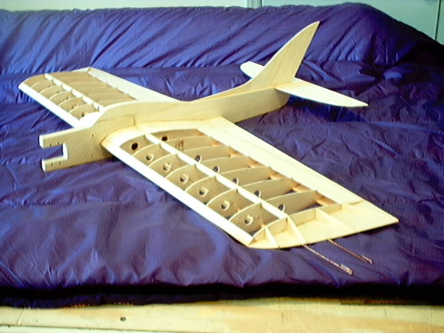
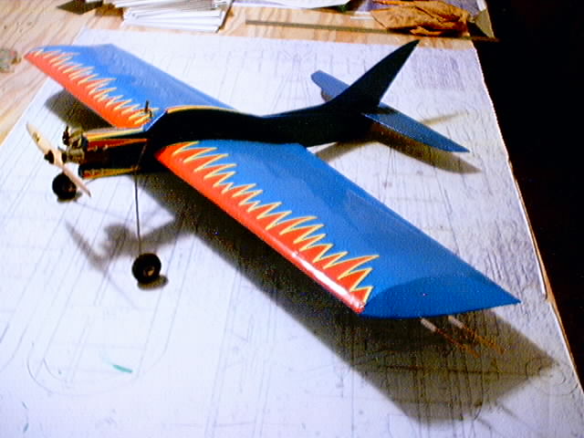
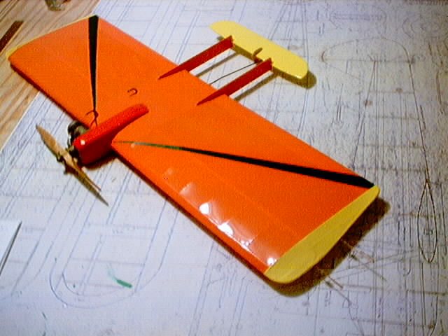
Can anyone help with a faster way to produce the ribs than the way outlined in the instructions?
Thanks in advance.
Doug Moon
Stuka Stunt Main Forum · 19 of 19 known posts recovered
Can anyone help with a faster way to produce the ribs than the way outlined in the instructions?
Thanks in advance.
Doug Moon

http://216.37.26.18/viewbyarticle.asp?issuenum=AMA8505&firstpage=74&articlenum=23&command=init
You'd have to cut the cores once, trace off the ribs, glue the cores back together again, then trace the other set of ribs...

Still, I can't understand why you are having problems, particularly with the actual diagonal rib sliced out of the foam wing. It doesn't make sense, that is literally a DIRECT measurement. (Are you building CROOKED, Douglas?) 
The eggcrate wing is exotic looking, but is labor intensive!
[photo not recovered: 3e69bb3870f12ad5.jpg]
"I was married by a judge. I should've asked for a jury." -George Burns
Geo Desic, and Geodetic are terms often mixed up with Warren Truss style construction which Bob hunt uses in his Lost Foam building system.
The whole design purpose of the Lost Foam System is to get each rib perfect and shaping them with the template is most likely the only way to get it perfect every time.
As for saving time on making ribs a good Auto Cad guy like Larry Cunningham or Robin Sizemore. Then have your ribs done with the Laser and have Bob Hunt do the jig with the laser cut templates you might get a better fit. The types of lines the laser likes best are Polyline, C-Curve, Arc and Spline.
Larry
[photo not recovered: roto-zip.jpg]
You can buy a rotor zip cutter at Home Depot or Lowe's for $49.95. The white 3 leg table is made from a piece of kitchen counter top. Mount the zip cutter on the under side. The 1/8" cutter needs to stuck up so the round smooth shank rubs on your templete and the cuttering blade of the cutter sticks up above the templete.
I have templetes for the Sterling Ringmaster, Flite Streak, Voodoo, Nobler, Stearman, and others.
An airplane like the Voodoo and Flite Streak takes only 2 wing templetes. All of the ribs are the same in these airplanes except the 4 center ribs that are a tad bit smaller for wing sheeting.
You can cut a 1/2" of balsa at a time with no problem. I can stick 8 sheets of 1/16" balsa on the Flite Streak templete and cut 8 ribs at a time. It takes about 2 minutes to cut 8 ribs.
This Flite Streak was built from Scratch. If you want notches for the spar and holes for the lead out wires all you have to do is cut notches and holes in your templetes.


This Voodoo was build from Scratch too. I built all the templetes, made the balsa parts and built the airplane in one Saturday. It took me 3 hours Sunday to put on the monocoat.

This Sterling Ringmaster was built with the Roto Zip.
[photo not recovered: ringmas1.jpg]
The Stearman Bi plans was built with the Roto zip too. One wing templete was all I needed to make all the ribs because all the ribs are the same.
[photo not recovered: stearma3.jpg]
[photo not recovered: stearma1.jpg]
Gary Weaver
Gary,
Could you show a picture of the underside of your table. I would love to make one of these but am unsure of the method used to mount the roto-zip.
Thanks,
Finch
Larry
If is works good I will try it.
The Ringmaster and Nober both have tapered wings. I have a templete for each rib. It takes several hours to make the templetes for a tapered wing. Once the templetes are made making balsa parts is easy. I usually make only enough balsa parts for 1 airplane at a time. For a wing like the Nobler I could put 8 sheets of balsa on each templete and make 4 complete wing rib sets in about an hour. Enough parts for 4 complete wings. I have templetes for the elevator, fin, flaps, fuselage, wing tips too. I usually don't make a stabilizer templete its faster to cut it with a razor knife sence its usually a straight cut on both sides. The El Diablo is the only wing stabilzer templete I have.
Gary Weaver
In our never ending search for the perfect wing building method John Simpson and I have tried at least a dozen different configurations. The "Lincoln Log" wing building method solves a lot of wing building problems and produces a really great wing, but you still have to cut out a set of sheet ribs which takes six sheets of balsa and about 2.5 hours of somewhat tedious work.
John came up with the idea of combining the "Lincoln Log" three piece leading and trailing edges, the I-beam rib slices and the Nobler type "D" tube sheeted spar construction. Now you can cut out the rib slices with a simple jig (See page 52) in about ten minutes using less than two sheets of balsa. Alleluia!
The spar height is determined by the root and tip rib thickness’. The spar is notched 1/16" X 1/4" at each rib location. The 3-piece leading and trailing edges are not notched, only marked for rib locations. The rib slices are trimmed at the tail for length and depth. The plywood bellcrank mounting plates are inset on the top of the spars directly under the sheeting. The landing gear blocks are supported on each side by 1/32" ply doublers. The vertic1e landing gear blocks are full depth and glued firmly to the sheeting, both top and bottom, ply doublers and against the spar. The inboard spar is notched to allow the leadouts to clear when the adjustable is all the way forward. Leading edge, trailing edge and center sheeting is as usual for a sheeted "D" tube wing.
The wing tips are fully sheeted with 1/16" balsa. Also notice that the outer bay is sheeted per Robin Sizemore's suggestion. This increases rigidity at almost no extra weight. Also, it allows symmetry in the open bay with round fillets on both ends. It looks better that way. Before the tip is sheeted another rib sliver is placed on the outboard rib to act a shelf for placing the tip sheeting. The sheeting is then glued to this ledge and to the tip perimeter. It makes a very strong, yet light and easy to finish tip. The adjustable is built right into the tip.
The only glue I use is Elmer's, period. On any surface joint, instead of a continuous bead of glue, I put small drops about every 3/8". This keeps the joint from being a hard line and showing up later as you sand. Sheeting is pinned in a few places, but primarily it is held down by steel weights. Once you get away from pin based building to weight based building, your speed will pick up significantly. I have all sizes and shapes of weights in my shop. I use them in nearly every building step. Another plus is that weights hold everything dead flat on the bench. These wings come out of the jig blocks dead straight every time.
Once the sheeting is completed, except one piece of the center sheeting to allow access to install the push rod, it's time to shape the leading and trailing edges. This is done with a Stanley 12-101 razor plane. Pull the razor plane toward you instead of pushing it away from you. You rest the heal of the plane on the sheeting and plane until you hear the clicking of the glue joint from the dots of glue. With just a little practice you can shape the leading and trailing edges in just a few minutes so accurately that you can go straight to sandpaper bypassing the Perma-grit file.
I am currently building these wings for 50 Cavalier "Quick Build" kits to be available in March. I will try to make a video available in late January.
I truly believe our search for the best wing building method is over. We've found it! This is it!
Doug, I plan on sending a set of ribs for a certain "Geo" wing to a certain laser cutter so that he can scan them. He scanned my templates for the Grondal Nobler. Have y'all tried this?
Remember, I am pretty ignorant as to the whole laser "set up" business. 
Bill
Dont worry about the mule going blind 'til you get the cart loaded!
One could carry it a little farther and make a pin router by mounting the RotoZip above the work surface and putting a 1/8 inch pin in the table. If there was some way to harden the foam rib templates you could just stack the rib blanks on top of the actual foam templates and cut them without having to make plywood templates. The biggest problem is coming up with a support heavy enough to keep the RotoZip in alignment.
With the Pin Router the template wouldn't be pressing against a guide that is spinning and should last longer.
This is sure making me think about ordering a lost foam wing or two..
Richard:
It's been said that your Maverick staarted out with a know design with some changes, is this true and which one. I might have it in my collection and would like to build the plane with your changes. I have most of the SV series in lost foam.
Don
Doug Moon
Doug;
I am sure there is a way in CAD to do this, but I just haven't figured out the last piece of it. Here is what I have been able to do to date with Autocad:
1. Lay out the root and tip ribs. Chord is along the X-Axis, thickness is along the Y-Axis. Rib templates include spar notches, LE notches, etc. The entire rib is converted to a polyline.
2. Place the ribs along the Z-Axis to reflect a wing panel.
3. Rotate the drawing so that I can get an oblique look at the LE and TE templates.
4. Create a surface that runs between the root and tip templates. This gives me what appears to be a 3D wing.
5. Change the view so that I am looking straight down at the wing.
6. Slice the wing in the pattern that I would want the ribs to go.
7. Seperate the slices.
Once this is done, I have a number of "sliced wedges", eg a virtual disected wing. The surface where I sliced the wedge the exact same outline as the wing rib would have, to include all notches. The trick is to convert that sliced surface into a rib.
What I have not been able to do is to extract that outline from the sliced surface. If I could, I would be able to put together a collection of ribs, arrange them on a balsa plank layout, and generate a simple .dxf file that could be send to the laser cutter. This way, one would have infinite repeatability to generate ribs using the same foam buck or cradle.
To be this close is maddening. Any CAD gurus that have and hints or ideas would be most welcome to chime in here.
Regards - Bob Kruger
[photo not recovered: 3f7994bd6ea47e23.jpg]
Here is the information I need to feed Stuntrib:
1. Root chord length <root chord would be at center of fuselage>
2. Tip chord length
3. Root maximum thickness
4. Tip maximum thickness
5. Thickness taper method (straight line or elliptical)
6. Finished trailing edge height
7. Thickness of planking
8. Length of wing panel (root <center of fuselage> to tip rib)
9. For EACH RIB:
a) Distance of its leading edge from the root rib
b) Distance of its trailing edge from the root rib
BTW, there's nothing that difficult about using Stuntrib, it is simply an old MSDOS program that has to be fed this information as text data, for each rib. Although you can manually type in the data, I normally set the information up as a text file, which is then fed to Stuntrib as an redirected input file, and its output goes to a redirected output file that you specify a name for.
I make up one of these rib data input text files for each rib (the only different information is 9a and 9b, so I use a text editor to do it), then I normally create an MSDOS batch file which you can execute to make up the entire set in a few seconds.
This is all described in the documentation file included with Stuntrib and I have provided sample rib data files and a batch file which makes up a set of 10 Mo'Best ribs in about 10 seconds..
The output DXF files can be imported by any modern CAD program. They are already in the form of two POINT entities, two LINE entities, and two POLYLINES. A CAD program can remove any unneeded parts (e.g. points for LE and TE, dotted center line, and outside planking polyline) and collect them on a single drawing for the laser cutter.
[photo not recovered: 3e69bb3870f12ad5.jpg]
"When I was born I was so surprised I didn't talk for a year and a half." -Steven Wright
Don