Stuka Stunt Control Line Forum
Archive, 2000–2021 · recovered from the Internet Archive
Forums › Stuka Stunt Main Forum

Airfoils...

Stuka Stunt Main Forum · 55 of 55 known posts recovered · the forum listed 68 replies

Serge Krauss · Dec 06, 2003 01:34 AM

edited#1 source
>Speaking of Stunt airfoils - does more thickness really mean more lifting ability, or are the
>really fat Stunt airfoils used mainly because they have a lot of drag? Does a 25% wing really
>lift more than a 15% wing at the same alpha? Does it have a larger maximum alpha?

Igor seems to have the best data on stunt airfoils and has posted several opinions regarding actual lift and attack angles needed. What I have is mostly old NACA data. TR 586 lists maximum lift coefficients for the NACA 00XX series sections at Reynolds Numbers between 150,000 and 1,300,000 in this ascending order: 0009, 0012, 0015, 0018. TN 364 shows the 0021 at a still higher CLmax and indicates that CLmax benefited by using turbulating screens above about RN = 100,000. Lift curve slopes were in reverse ascending order.

These relationships did not hold under all circumstances. For instance, at lower and higher RN's some of these relationships changed, notably at both (lower) critical RN's and nearer to full-sized aircraft RN's, where the CL max dropped off again at thicknesses above 15-18%. Also, the tunnel mount interference effects were reanalyzed about this time and "effective" Reynolds Numbers were computed and revised.

My feeling is that the leading edge radius and transition to "high-point" are of primary importance, and probably the reason thickness seems to correlate with CLmax data, since thickness limits curvature and chordwise pressure gradients. So they influence both lift and drag. I agree that the drag is important in stunt as a limiter to speed change. Again, Igor has written some interesting analysis of the behaviorof thin sections at the RN's of stabilizers though. Some interesting changes occur in lift curves for wings approaching that size, making wing loading much more critical there. Perhaps he will comment on this thread.

>(Tu - Td)/Tu = 2m*g/Tu

>= 2m*g/(D-m*g)

'nice demonstration of high drag's influence on % thrust variation. However, I think you meant to type "(D + m*g)" in the denominator. Yes?

SK

Iskandar Taib · Dec 06, 2003 09:26 PM

#29 source
Yup, there's a typo there. I suppose it depends on what you wish to use as the denominator, but Tu would probably be the best choice.

Rustler · Dec 06, 2003 01:34 AM

#2 source
Hence we use the 4/2 motor run. The 2 stroke portion is useful on the climb, seeking to maintain constant airspeed. This is why I never can understand the logic of those people who claim "Yes, 4/2 is desirable, but as little switch as possible". It seems obvious to me you CAN have too much break, but I've never yet seen it. You get it when a model accelerates in the climb and slowws down in the dive!!!!

Brett Buck · Dec 06, 2003 11:17 AM

#12 source
>Hence we use the 4/2 motor run. The 2 stroke portion is
>useful on the climb, seeking to maintain constant airspeed.
>This is why I never can understand the logic of those people
>who claim "Yes, 4/2 is desirable, but as little switch as
>possible". It seems obvious to me you CAN have too much
>break, but I've never yet seen it. You get it when a model
>accelerates in the climb and slowws down in the dive!!!!

Not quite. A 4-2 break does essentially nothing in the corner, so the airplane just slows down. Later, in the subsequent straight line, it then accelerates back up towards the original speed. If it's still accelerating when you turn downhill, then now you have a lot of acceleration from the engine, and also are aimed at the ground, and it's off to the races. It's of course a matter of preference how much of this you want to put up with, but for my money it's not very much at all.

Of course, a 4-2 break is no longer necessary to get regulation. A piped engine responded *immediately* to the load - the first pressure wave that arrives closer to "on time" helps right then - and of course the prop just in and of itself is better at holding the speed in the first place, so very little 4-2 break is necessary, and for my money in combination with a tuned pipe and a high-rev/low pitch prop, if very easily results in the "excess power" problem mentioned above. Reducing the compression until it's tolerable just makes it gutless all the rest of the time. I've flown 4-2 breaking TP systems where you would go into a round loop, and about 45 degrees in, the engine kicked in and it darn near yanked the handle out of my hand. That's not conducive to precise flying - and even more so in the square 8 when it "kicks" halfway up the intersection and then stays "kicked" due to the "schneurle effect", peaking about the time you turn to dive at the ground.

One solution - use a large enough motor with enough compression and nitro, and a small enough prop, that it has sufficient power to fly the whole pattern in a 4-stroke. The small prop doesn't "feed back" as much to the engine, and thus doesn't transmit the load enough to trigger the "bursts". Another solution is to run it with little enough pitch that it flies the entire flight in a 2-stroke.

A 4-stroke engine is the ultimate in this idea. But, as implied by your comments, it doesn't regulate the airspeed much at all, having very weak regulating mechanisms . That's why they tend to run pretty fast in level flight but still have respectable maneuver times/speed. The current "debate" at the bleeding edge of the event seems to be shaping up to be - is the large amounts of line tension (and thus stability in turbulence) and dead-soft response of the 4-stroke "better" or "worse" than the superior speed stability of a properly-running piped setup, that seems to be more capable of rulebook performance in smooth wind and dead calm?

By the way, one thing Ted and I both liked about the Rustler-Merco 40 with a 10-4 3-blade was the silky smooth power delivery with very soft break. It may well be that you have never run across one of the "jato bottle" 4-2 break piped setups. Or, a 40FSR with a muffler and a 12-6 prop!

Brett

Rustler · Dec 06, 2003 04:47 PM

#19 source
Ah yes. For me the ideal break is one which occurs the instant the nose turns up. We strive to get it, but that is also something I have never seen! Many don't break until the model has reached e.g. in loops and square manoeuvres, the 45deg. height, by which time it's a bit late, but better late than never?

John Sunderland · Dec 09, 2003 11:35 PM

#62 source
>Ah yes. For me the ideal break is one which occurs the
>instant the nose turns up. We strive to get it, but that is
>also something I have never seen! Many don't break until the
>model has reached e.g. in loops and square manoeuvres, the
>45deg. height, by which time it's a bit late, but better
>late than never?

On round maneuvers I liked the 4-2-4 on at 10 oclock and off at 2 oclock. Biggest trouble (in my opine) with this engine run is lack of grunt toward the end of the square eight and the fact that wind up in the heavy wind is more pronounced.

Rustler · Dec 06, 2003 04:49 PM

#20 source
Brett, you'r right, I've never run across one of those. Jet assisted take off? If not too much trouble, could you explain?

Ty Marcucci · Dec 06, 2003 02:20 AM

#3 source
Ugh, what??

Serge Krauss · Dec 06, 2003 11:44 AM

#14 source
Now, Ty-

You just need to repeat to yourself that "equations are my friends, equations are my friends, equations - are - m...zzzz".

Seriously, Isky's last equation seems an eloquent and understandable explanation of why higher drag stunters should have more stability in speed. The last expression
"2m*g/(D+m*g)" (corrected), is just a fraction whose numerator (top) is "2 m*g" and denominator (bottom) is "(D+m*g)". Since m (mass) and g (the acceleration of gravity) are constants here and weight (W) = m*g, this expression is just 2W/(D+W), where D is the only quantity that varies. We all know that as the denominator increases in size relative to the numerator, the value of the fraction decreases. So as Drag (D) increases, the fraction becomes smaller in value.

His last equation then just shows that as overall drag increases, the percent difference in upward and downward thrusts diminishes, thereby diminishing the percent difference in maximum speeds. This would be true even if drag did not increase at all with speed. It's an added speed-stability "bonus".

Serge

Ty Marcucci · Dec 07, 2003 01:14 AM

#32 source
Yes, I fully understand all this and it is exactly what ol Wilbur and I discussed back in ought three. Yeah, right.

Al Rabe · Dec 06, 2003 07:58 AM

#6 source
The "Go For Broke" article was reprinted in Stunt News a year ago in the November/December 2002 issue. For what its worth, I believe that thicker airfoils do create more lift and I don't use blunt nosed airfoils. Snaggletooth flew with a home made .60 and 550 sq. ins. of wing area and turned well with a pleasingly tight corner. My 1978 article "Evolution of a Thoroughbred" published in Flying Models and Aero Modeler also contained my thoughts on wing and airfoil design. It was reprinted in the March/April 2000 issue of Stunt News.

Al

LNeumann · Dec 06, 2003 08:41 AM

#7 source

>As far as the thrust and drag relationships, there are two
>effects you need to consider. First, the drag will go up
>with the square of the velocity, and the thrust will fall
>off linearly as the airspeed increases. The only constants
>(and actually, even they change minutely) are G and m.
>
>
Interesting, because in my e-mail conversations with Igor he stated that thrust did not fall of linearly as the airspeed increases. It was a question I had (and still have) because I always figured about 9 to 10$ "slippage" (or difference between calculated, theoretical maximum, air speed and actual airspeed due to drag)

Brett Buck · Dec 06, 2003 12:10 PM

#16 source
>
>>As far as the thrust and drag relationships, there are two
>>effects you need to consider. First, the drag will go up
>>with the square of the velocity, and the thrust will fall
>>off linearly as the airspeed increases. The only constants
>>(and actually, even they change minutely) are G and m.
>>
>>
>Interesting, because in my e-mail conversations with Igor he
>stated that thrust did not fall of linearly as the airspeed
>increases. It was a question I had (and still have) because
>I always figured about 9 to 10$ "slippage" (or difference
>between calculated, theoretical maximum, air speed and
>actual airspeed due to drag)

You are correct, it doesn't fall of linearly with airspeed - although just like anything, over a short range you could approximate it that way, and it may be reasonable in the case of small variations that you see in-flight.

The slippage is way more than 10%! Unfortunately, given our inability to make a reasonable static measure of pitch, we probably have no way of knowing. The only way I can think to figure out how much is to set up an engine on a thrust stand, pick the prop of interest, and run it at a constant RPM - then apply an ever-increasing airspeed until the thrust goes to 0. Then figure the real pitch by dividing the airspeed by the RPM. Now you have the true pitch, and then you can figure the "slippage" given the measured in-flight RPM, and pitch, to find the "theoretical" forward speed, then divide this into the actual speed.

Just based on efficiency guesses, I would imagine that the "slippage" in the case of stunt planes is more like 30-40%, depending on the prop - or advancing about 60-70% of the "theoretical" ideal. Note that the efficiency (hp transfer ratio) is 0 at both 0 forward speed (lot of engine HP, 0 HP gong into airframe) and at the "theoretical ideal" (because no thrust it being applied, no work is being done, so the "work rate" i.e. HP, is zero).

Based on the approximate pitch "correction" factor (measuring the camber and high point, and from that calcualting the angle of the zero-lift line using the approximation shown on the Joe Supercool site), and in-flight RPM measurements, I get something around 65% of theoretical which seems quite reasonable. If you don't correct for the airfoil camber, you get something like 150%, or going way faster than "physically possible"!

Brett

Igor Burger · Dec 06, 2003 03:12 PM

#18 source
Hmmm.. from 9% to 40% is really far way. I actually did a calculation exactly as Brett wrote. I did a prop with constant pitch rotating at some rpm making 0 trust at our speed. I assume theoretical lift without any lose of effective pitch on tip as we count with relatively small thrust in level (but anyway, it is rather optimistic calculation). And I assume that the drag is 5N in level. I got, that you have to slow down by:

8% if you have 12”x4” 3 blade prop.
19% if use 12x6 2 blade prop
30% if use 10x6 2 blade prop

Igor Burger · Dec 06, 2003 03:09 PM

#17 source
aaaahhhh, I got it already, the "$" and the "%" is close on your keyboard ... sorry it is 10% I see it now

Howard Rush · Dec 06, 2003 05:13 PM

#22 source
Oh

Ty Marcucci · Dec 07, 2003 01:18 AM

#33 source
That's what I thought. I just pray no newbies come to this thread, unless of course they are engineers of some type. Diesel Mechs are really ready to build a nice kit and use the engines and props ya'll talk about.

Igor Burger · Dec 06, 2003 09:01 AM

#8 source

>>>Does a 25% wing really lift more than a 15% wing at the same alpha?<<<
Definitely NOT. You can count that every airfoil makes lift cl=0.11 per 1 deg AoA. Thicker airfoil makes little but really only little LESS (well circle does not make it at all ). Clearly there are conditions: it is true only in linear (free of separation) segment of polar around 0 AoA and second – it NOT a rule that airfoil makes 0 lift at 0 AoA.

The fact that thicker airfoil makes more lift is only side effect:

>>> Does it have a larger maximum alpha?<<<
Yes and not. Serge already mentioned it, but I will add little more words. The blunt LE is that most important property what allows more AoA. Just because it separates later at LE.

I do not what to start another flame about Bernoulli, but reason has something to do with mechanics how the lift appears.

First of all, it is necessary to forget Bernoulli equation as reason of lift. It is only simplified tool to evaluate pressure. It is not answer WHY. It is the same like that thing about static pressure in liquid. Truth is, that not the speed is reason of pressure; it is acceleration causing that speed. Jut one clever guy did a derivation and the result is that equation telling how much, not why. So if there is speed difference then there is also acceleration forcing something somewhere and pressure is result of that acceleration. That is EXACTLY what was around that gravity and prop pull.

That accelerator is wing surface. It is curved and if flow must follow the surface, it is accelerated, that makes pressure difference.

And now comes the trick. If you force it strongly (more curved) you can get better pressure difference. But if you do it too much or too long (in time and thus in distance down the chord), it can happen that some particles are turned too much and a stream can run UNDER and agains those incoming and thanx sub pressure on top of airfoil they go back to LE between the surface and sream from LE. That kills that subpressure causing acceleration (and curvature) and flow over airfoil will follow straight and there will be a vortex between that flow and surface of airfoil.

So by other words, you can strongly turn the flow on LE, but at some AoA it separates. If you do LE blunter it will separate later (at higher AoA). That is reason for blunt LE.

Now let’s continue down the chord – you can not keep that radius too long, because it will happen the same (separation), means the radius must be less and less down the chord. If that has to be true, you will go from your chosen radius to some high point and then you continue down and down with slower and slower radius (that is main idea of those “equation” based airfoils like NACA). So the maximal thickness and its place is just matching of surface to the leading edge to keep surface aerodynamically smooth.

So we really use thick airfoil to both – making lot of lift and also the drag is rather positive, if we have enough power.

But we have also little different approach. We keep as small area as possible (enough for level fligh), and we are asking for lift only when we need it – in maneuvers. We do it by flaps and thus difference in chamber. The chamber brings some extra lift on top of that coming from AoA. It does not change what is happening on LE too much, it just helps to force more volume of air from under the airfoil over it and thus make more lift. But it does not change maximal AoA too much. And it costs come energy and thus drag.

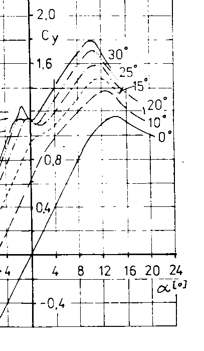
So I would say there is another side. (And yes, now I am heating my own soup ). Every airfoil has good properties at some mode and wrong at another. If you can optimize the airfoil for making lot of lift with relatively smaller drag, and let it make the drag where it does not make lift, you will get another advantage. That is one of things (beside maximizing of linear segment and suppressing of that “bump on polar” problem) what I did with my airfoil. The real problem of our airfoils is, that there are no universal airfoils optimized with large flap at 30 degrees deflection. They are optimized without deflected flap. If you take my airfoil and look at deflected flap, you will see smooth upper surface including hingeline. But in level, with flat flap, its shape if far from “good” and smooth so it brings little extra drag. The result is lower drag in corner and little excessive drag in level. If you combine it with properly matched leading edge radius what gives resistance to separation on hinge corner (there is no such corner) till high AoA you will get that linear segment over all usefull AoAs from 0 till 10deg. Its best gliding ratio and also its minimal drag with flaps at 30deg is at maximal lift over cl=2. You can find theoretical polar on:

http://www.netax.sk/hexoft/stunt/notes.htm

If you compare it for example to Wortmann FX71, which has only small peak of low drag at cl=0.8 close to 0 AoA and drag over and under is far far higher, you will clearly see what airfoil is for what. While FX is primarily designed for tail, then low drag at 0 AoA is big advantage, but it is not what we need, we need airfoil making low drag at its max lift.

igor

Chuck Smith · Dec 06, 2003 04:58 PM

#21 source
Good points Igor. Just a word of caution though. Using standard wind tunnel data is a little risky in evaluating the aifoil performance on an airframe. Wind tunnel data is generally done with full width sections, and is hence, 2 dimensional flow. It needs to be corrected for wing geometry and converted to 3d to give Clmax for a given apha. In 2D flow, there is no induced drag (in the traditional Biot-Savart sense), and the effective angle of attack will be pretty much the same for a given 'geometric" angle of attack. The higher the aspect ratio, the less the nose can go up relative to the freestream velocity before separation occurs. For instance, a NACA 2412 equipped sailplane begin to stall at around 14 deg, but the same airfoil on a delta winged jet would go well past 20.

Also, the thicker airfoil has a higher wetted area, and the flow is at a slightly higher Reynolds number than a thinner wing near the TE, so the adverse pressure gradients will be slightly higher, resulting in higher vorticity and hence, higher drag.

As far as the thrust, I'd still say for a linear approximation is a valid assumption, and is used in aircraft design. You have to remember there is a lot of entrainment of the air going into the prop disk at a static condition that falls off as airspeed increases too, so relating airspeed to AoA is again, risky. When we speak of propeller pitch, even though it actually varies across the span, it is generally accepted as the pitch at 75% of the span. Some companies use 70%, but 75% seems to be the industry standard now. Course, I usually treat the prop as a black box and as you have noted previously, use a momentum balance to predict thrust, which has worked well for initial sizing exercises.

Luckily we have the best situation on a stunter. We can easily change props and whatever works best, go with it!

Igor Burger · Dec 06, 2003 05:22 PM

#23 source
>>>As far as the thrust, I'd still say for a linear approximation is a valid assumption, and is used in aircraft design.<<<

It is very difficult with that linearity. When Len mentioned that question, my original idea was, that if it would be true, then it would be simple to measure static thrust on ground at rpm for proper speed in level flight. Then if you know the static thrust, and you know it is linear, you can simply derive the response of thrust to change of speed – or – the speed stability. But we know that it is not true. If you do the math and you know RPM and if you take prop like 10x6 you will easily see that even tip of prop has angle which can not safely make thrust – or – as you launch your model, the thrust grows, and that has nothing to do with linearity. The experience says, that 12x6 prop almost does not pull on ground and start with such prop is very slow, especially on grass, while 12x4 prop, which has tips at good conditions strongly, pulls on ground. But it is still far from linearity if you take speed from 0 to our regular speed. I do not know how it is on full-scale props, I guess they are large enough to count with linearity also at 0 speed, but static thrust on our models is completely out of sense and does not say anything about quality of power train or prop.

But yes, I do agree that in range +/- 10% from our speed you can really count it is more or less linear, especially with modern low pitch props.

Howard Rush · Dec 06, 2003 05:24 PM

#24 source
So when you wrote. "In very general terms, the thicker airfoil will have a steeper Cl vs. Alpha curve.," what you really meant was that a high aspect ratio wing with a thick airfoil has a steeper Cl vs. alpha curve than a low aspect ratio wing with a thin airfoil.

Chuck Smith · Dec 06, 2003 08:41 PM

edited#28 source
>So when you wrote. "In very general terms, the thicker
>airfoil will have a steeper Cl vs. Alpha curve.," what you
>really meant was that a high aspect ratio wing with a thick
>airfoil has a steeper Cl vs. alpha curve than a low aspect
>ratio wing with a thin airfoil.


Now that I think about it, that statement is false. For a symmetrical airfoil, the curve of Cl vs. Alpha will be 2(pi) regardless of thickness. Positive camber will move the curve to the left. What will change is the way the airfoil responds as it appoaches the critical angle of attack. Thinner, sharper LE airfoils can have a separation bubble which reattaches, whereas the thick airfoil will have a TE separation that moves forward with increasing AoA. Mr. Rabe's airfoils have always fascinated me. I remember watching his Sea Fury fly, not sure if it was Oshkosh or Lake Charles. (Both? Was the P51 at Lake Charles?) The thick airfoil, combined with the thin flap always made me wonder if the (one would think) high adverse pressure gradient at the front of the flap had the airfoil operating in a controlled separated condition, and thus set the moment coefficent (fairly) constant while retaining a high lift coeffient. The result would be, of course, a wing that gave high lift but had a low moment - resulting in an airplane that would turn on a dime. In any case, it was impressive to watch. Of course, a lot of that could have been pilot too! As an airfoil creates more lift, it also creates a pitching moment. So the more you pick up the nose, the more it resists - until the flow starts to separate and then the moment becomes pretty constant.

The aspect ratio determines the induced drag, and high aspect ratios have lower spanwise flow, so the effective angle of attack will be closer to the "actual" angle of attack. In other words, given two airplanes with the same airfoil, the one with the lower aspect ratio will be able to fly with the nose higher before stalling. So in stunt, one might surmise, that, due to the aicraft having a power to weight ratio in excess of unity, the thrust vector will have a different effect on how the airplane turns when comparing a high and low aspect ratio stunter. I would love to see one of the old U2 stunters fly to see if it is noticable.

As far as thrust linearity, I'm still sticking to linear or pretty darn close. When evaluating required power, one plots the parabolic drag polar for the aircraft vs. airspeed. Next, the thrust vs. airspeed is plotted on the same graph, and the area between the curves is where the airplane will fly. The area above the drag polar but below the thrust curve is where you can climb. As an aside, this is where the phrase "behind the power curve" comes from. Even for fixed pitched props, the thrust curve is pretty darn straight. As mentioned previously, the prop is treated as constant pitch with a value of the pitch at 75% of the blade length to give the *advance ratio*, which is used to evaluate the prop performance.

Let's look at a 6 inch adavance turning at 11000 rpm. Doing the sums, and figuring 80% efficiency, the prop is advancing at 50mph. So if we go faster than 50, the prop is braking, right? Nope, as it moves past 50mph it loses it's slip, and it becomes more efficient. In fact, at 62.5 mph it becomes 100% efficient. So, the airspeed would need to increase by 25% before it starts braking. Actually, I took some liberty and simplified the situation, but the end numbers are pretty close. What it demonstates, however, is that a prop has the ability to smooth out its own performance and hence act pretty linear.

Serge Krauss · Dec 06, 2003 09:53 AM

edited#10 source
>In very general terms, the thicker airfoil will have a steeper Cl vs. Alpha curve.

As I noted above, the early NACA data (TR 586, written after wind tunnel interference effects were noted and accomodated) indicates the opposite for non-flapped NACA 00XX sections in the 150,000 - 900,000 Reynolds Number range, at least through 18% thickness. In ascending order of lift-curve slopes, the section order is 0018, 0015, 0012, 0009. As you noted, the thicker sections have the more rounded off curve. Thus, the thicker sections stall more gently and later (higher aoa). Your stall progression probably accounts for that. This data was for flapless sections.

What I did not address in my earlier post is data for flapped airfoils, which would be more pertinent to this discussion. That is why I think that Al's and Igor's data are particularly pertinent. FWIW, at our stunt Reynolds Rumbers, this early report shows that, in an NACA 5-digit section family (23012, 23015) using split flaps, the thicker one had the highest CL max. Al's findings certainly support that trend. I might also point out, in support of what I said about l.e. radius and transition curves in my first post, that even though Al's l.e. radii are not nearly the maximum possible with his thicknesses, they don't seem minimal either. I don't think I have other flapped data at low RN. Perhaps Martin Simons' book too has something to say about that. If I have time later, I'll check it.

One thing seems apparent. When you decrease to critical RN's, the thickness and leading-edge requirements seem to make thinner, sharper (turbulated) sections more attractive - at least that's what I gather from old NACA graphs and earlier posts on SSWF.

>As far as the thrust and drag relationships, there are two effects you need to consider.
>First, the drag will go up with the square of the velocity, and the thrust will fall off linearly
>as the airspeed increases.

I think Isky's point was that as the minimum drag coefficient inreases with thickness, the thrust required to fly a good pattern is increased by engine/prop choice to accomodate that. He demonstrated that the general trend then in choosing greater thrust is to reduce the percentage difference in thrusts available to climb and descend (through engine run characteristics).

SK

Edit: Again, I see that Igor types faster than my two fingers - this time two posts to one!

Howard Rush · Dec 06, 2003 11:32 AM

#13 source
"I do not know what you mean “9 to 10$ of slippage”"

That means should pay more for your propellers. Expensive carbon props must not slip as much.

Igor Burger · Dec 06, 2003 07:33 PM

#26 source
Al,

I feel some problem with the word “my” I used in relation to that airfoil. So let me tell you I did not invent airfoil, I did not invent flapped airfoil, and I was too young to be “at” fist usage of flapped airfoils in C/L stunt. I also never said there is something revolutionary new with that airfoil. The only what I ever wrote is, that as far as I know (I note that word “I”) than there is nothing to make better. Or by other words, that airfoil is good enough, there is nothing what we will need better. AND!!! I never wrote it is the only airfoil, which is “enough”. Guys who was present at that time on old CompuServe and RC online will probably remember when I compared “my” (well I did not invent name yet, so sorry for that “my”) airfoil to other which I analyzed – it was Supermaster (flown by Gabris 2x WC champion), and airfoil published on full size US plans available for me – Cardinal, Juno, Dreadnought and Trivial Pursuit and some universal flapped airfoils dedicated to full scale airplanes.

As you see your airfoil is not there, just because I did not have airfoil data with enough precision. But anyway, I do not intend to go your way with asymmetric airfoil because it does not make sense in my eyes, we already spoke about it if you remember.

The reason I did that airfoil was, I got chance to make theoretical analyze on serious software in winter 1997/98. The first disappointing question of that guy was: “what airfoil you want?”. He told me that it is easy if we can say what we expect, but I was not able to say “what is that what we want”, and thus I stared to play with it deeply.

I did analyze of really measured airfoils to compare results and to know how far I can believe it and I did analyze of those successful and also less successful airfoils to know what is that “what”. The result was the “bump on polar” effect, attempt to solve it and then attempt to optimize the airfoil for range RE=200 000 till 500 000.
My criteria was following (most important on top):

1/ As long as possible linear section (also means free of bumps)
2/ As low drag at maximal lift as possible
3/ As much lift as possible (result of point 1/)
4/ Dedicated for foam wing construction


I did around 30 trials in 2 months with mixed results. It was really eye opening and I believe I would not do such amount of tests on real wings. I note some of them was with modeled circular flow in corner – no way for real tunnel measuring.
The point 1/ was successfully solved, point 2/ was just optimization, without too much care, 3/ … I was surprised with value up to cl=2.5, 4/ no problem, the problem is with spar and open bay construction

Then I did my first model “Next”, its clone with more wing load called “Max”, and set of small stunters “Tiny” and “Middle”. All of them fulfilled all expected properties as I calculated before building (that also says what is the repeatability – no more rule “make two same, you will get two different”) and thus my conclusion was: that is that “my” airfoil.
So please understand the “my” expression that I like that airfoil, I use it, I believe it, but I do not keep any “patent” or “copyright”. If you want, use it, if not, use your. I cannot say it is winner of US NAT, because it probably never participated, but I can tell you if we would do championship of Slovakia, it will certainly win … guess why .

To make the story short, the answer to your question:
>>>Do your airfoils differ in any significant way, or are we just technologically reinventing the experimentally derived wheel?<<<
It is usage of existing knowledge for optimized airfoil with lot of care to details till the amount of effort I was willing to invest. That is all.

But I must write here one note. The airfoil is really only one small part of equation. Successful or unsuccessful design cannot be concentrated to only good or bad airfoil and certainly not to “more” or “less” lifting airfoil. The airfoil is just one of thousands things which have to be done well on the model nothing more nothing less.


Al Rabe · Dec 06, 2003 11:39 PM

edited#31 source
The only what I ever wrote is, that as far as I
>know (I note that word “I”) than there is nothing to make
>better. Or by other words, that airfoil is good enough,
>there is nothing what we will need better. >
> I do
>The reason I did that airfoil was, I got chance to make
>theoretical analyze on serious software in winter 1997/98.
>I did analyze of really measured airfoils to compare results
>and to know how far I can believe it and I did analyze of
>those successful and also less successful airfoils to know
>what is that “what”. The result was the “bump on polar”
>effect, attempt to solve it and then attempt to optimize the
>airfoil for range RE=200 000 till 500 000.
>>I did around 30 trials in 2 months with mixed results. It
>was really eye opening and I believe I would not do such
>amount of tests on real wings. I note some of them was with
>modeled circular flow in corner – no way for real tunnel
>measuring.
>>the “my” expression that I like that
>airfoil, I use it, I believe it, but I do not keep any
>“patent” or “copyright”. >


Why is it necessary to have coordinates to validate airfoil designs and concepts originating thirty years ago? I presume you have theoretical means to evaluate the incremental differences between the airfoil you (and I) favor and the top two airfoils displayed above. A visual comparison their general appearance would indicate that differences in their performance is probably insignificant.

Your opinions are based, by your own account, on theoretical analysis using serious software. Why should we believe that this theoretical analysis is based on sufficient criteria for symmetrical airfoils with flaps attached to the trailing edge to be valid? There is almost no data on this configuration, or did you create the data based on your theoretical analysis?

Thirty years ago, based upon crude experiments, (which might compare favorably with theoretical analysis) I concluded:
1. stunt airfoils would work better if we avoided the discontinuity at the hinge line. Therefore the shape of the ribs should flow smoothly over the flap hinge onto a deflected flap. On this we seem to agree.
2. the optimum flap deflection to create the best lift/drag ratio for symmetrical airfoils with trailing edge flaps should be about 30 degrees. Again, we seem to agree.
3. thicker wings potentially can make greater lift for a given area. I satisfied myself this was true, based on my experiments, and designed airplanes with intentionally reduced wing area for the same level of performance.
4. it is my opinion that moderate leading edge radius is more desirable on a stunt ship than a noticeably blunt airfoil.
5. wing lift for a given total area will be improved by using a larger percentage of flap. My typical flaps are about 25% of the total wing area. This conclusion was supported by a NACA chart included in the "Going.." article

There are probably less than 10 competitive stunt flyers in the US who could understand airfoil ordinates and make any useful application of the data. It is my opinion that there is negligible difference in performance between your computed airfoil and several of those displayed above. It is enough, in my opinion, to create useful, nearly optimum, stunt airfoils by simply copying the general appearance of the airfoils presented here. Why question the validity of computed airfoils versus crude experimental airfoils designed thirty years ago? They are obviously similar enough that either "airfoil is good enough, there is nothing what we will need better."

It is usage of existing knowledge for optimized airfoil with
>lot of care to details till the amount of effort I was
>willing to invest. That is all.
>

I guess that I resent the thought that your airfoil based on theoretical analysis has more validity than my very similar airfoils, experiments and reasoning done thirty years ago and published, if no longer much acknowledged.

Incidentally, did your computer analysis consider the effect on lift of flaps of various chord lengths? I intend to copy, on transparencies, our airfoils and overlay them to to point out the similarities. there are simply no copy shops open tonight. Again, I refer to the top two airfoils displayed above. There are three reference airfoils in my display. The bottom airfoil has a simple flap, embedded in the trailing edge. there is also a 15% test airfoil and a Nobler airfoil which I tested for reference and drew the conclusion that I could get more lift than any of these.

>I do not intend to go your way with asymmetric airfoil because it
>does not make sense in my eyes>. I'm sorry you do not understand the logic of my asymmetric airfoils. They are simply based upon the logical demands of the pattern and have proved to work well in practice. I have a good deal of experience with asymmetric airfoils for competition stunt. It seems you haven't gotten around to doing a theoretical analysis of the possible advantages of the configuration.

Igor, it seems we favor very much similar airfoils except that mine seem to have a slightly smaller leading edge radius. I found in the tests I ran that airfoils with sharper radius ran smoother and buffeted less in turbulent or gusty conditions which explains my preference for moderate radius. I'll admit the experience was subjective but seemed definite. You have certainly covered the ground on lift and drag but did your theoretical analysis delve into stability of our stunt configured airfoils and their likely ability to operate optimally under less than optimum flight conditions. Do your computations take into consideration varying "G" loading and angle of attack due to local flight conditions.

And I really am interested in your analysis of airfoils with different flap chords. Your flaps look small to me.


Al

Igor Burger · Dec 07, 2003 11:11 AM

#34 source
>>> Why is it necessary to have coordinates to validate airfoil designs<<<
Al,

I do not want compete with amount of effort, or used tools, or artificial impression of those airfoils. The only argument can be what are lift characteristics. The only simple way I know is the analytic polar, for which are coordinates necessary.

>>>A visual comparison their general appearance would indicate that differences in their performance is probably insignificant. <<<
They can LOOK similar, but I am absolutely sure they are NOT similar. If I briefly compare it, I see that you have far smaller LE radius and that is difference in most important place. Another argument is your own – it is asymmetric airfoil and you say it is different in one way than the other, so how it can be similar to my? Which side you mean?

>>>Why should we believe that this theoretical analysis is based on sufficient criteria for symmetrical airfoils with flaps attached to the trailing edge to be valid? There is almost no data on this configuration, or did you create the data based on your theoretical analysis? <<<
I am offering my experience; you can believe or not. If you do believe than OK, if you do not believe and do not want to believe it is your choice and if you do not believe and you want question or proof my approach, I am open to any mean full question or input. To that your question, which I understand as “how I proofed it”, my answer is:
I compared the analyzer to several REAL TUNEL data. I found very good coincidence and even more, I found that in range of small RE numbers such tool gives much better answers then polars from real tunnels corrected to low RE numbers. Such a correction is more or less estimation or better said guess and sometimes leads to significant errors. If I compared airfoils to those measured in real low turbulence tunnels (but such polars are very hard to find), then I got better coincidence then those ”corrected”. That convinced me I got good data.

>>>1. stunt airfoils would work better if we avoided the discontinuity at the hinge line. Therefore the shape of the ribs should flow smoothly over the flap hinge onto a deflected flap. On this we seem to agree.
>2. the optimum flap deflection to create the best lift/drag ratio for symmetrical airfoils with trailing edge flaps should be about 30 degrees. Again, we seem to agree.
>3. thicker wings potentially can make greater lift for a given area. I satisfied myself this was true, based on my experiments, and designed airplanes with intentionally reduced wing area for the same level of performance.
>4. it is my opinion that moderate leading edge radius is more desirable on a stunt ship than a noticeably blunt airfoil.
>5. wing lift for a given total area will be improved by using a larger percentage of flap. My typical flaps are about 25% of the total wing area. This conclusion was supported by a NACA chart included in the "Going.." article <<<
I agree, but it is really not the only way. Just look to airfoil on Trivial Pursuit, which does not have smooth hingeline. I did analyze also for that airfoil. That airfoil makes maximal lift very similar to that my. Also the polar is free of any bumps or other stupidities. And that is ESPECIALLY thanx of that blunt LE. I tried to make it sharper, and I got all problems I wanted to suppress – early flap separation and bump at 4 or 5 deg AoA with deflected flap at 30deg. The only reason why I did not use this approach was excessive drag in corner (means 30 deg flap and 7 deg AoA). But as I wrote already – there is no need to go to some extra big lift numbers, if we know that we do not exceed 10 deg AoA. So it enough to be sure that airfoil keeps linear numbers till that 10 degrees and that is enough, you not need anything more.

>>Why question the validity of computed airfoils versus crude experimental airfoils designed thirty years ago? They are obviously similar enough that either "airfoil is good enough, there is nothing what we will need better."<<<
I did not ask

>>>I'm sorry you do not understand the logic of my asymmetric airfoils. They are simply based upon the logical demands of the pattern and have proved to work well in practice. I have a good deal of experience with asymmetric airfoils for competition stunt. It seems you haven't gotten around to doing a theoretical analysis of the possible advantages of the configuration.<<<
I really well understand your arguments to asymmetric airfoil; I just do not see need or real advantage to do it. May be you remember I had two reasons against:

1/ If the airfoil is really good, model flies well, and do not stall or make any other troubles in corner, then there is NO difference between 120 deg corner and 90 deg corner. Both have the same radius; both have the same centrifugal force and thus they need the same lift. An IF … really IF the airfoil is not so good, or the model is too heavy or what ever brings you troubles that long leg of hourglass, then why not just make the airfoil thicker symetrically? You will just not use its whole capacity in negative corners.

2/ Clear counter question to my previous point is “why yes”, why to have it symmetrical, what is advantage. That is also several times mentioned on this forum. The zero lift AoA of asymmetric airfoil is not at 0 AoA. That will bring lot of problems to my precise designing. The real problem would be proper matching of engine thrust and stab and elevator AoA. You several times wrote you use coincidence –2 degrees, while all other 0 till 0.75, and that is the answer. You tried something, it works for you, you convinced me, you are happy with it. I did not see it, I cannot judge but I understand. However it is not my way, I will just do not do it, because I see another solution, which satisfies me better. I do not say it does not work, I do not say I cannot understand it, I just say I do not want go this way.

Al Rabe · Dec 07, 2003 02:21 PM

#37 source
Let's start with an easy one first.

Igor,1/ If the airfoil is really good, model flies well, and do
>not stall or make any other troubles in corner, then there
>is NO difference between 120 deg corner and 90 deg corner.
>Both have the same radius; both have the same centrifugal
>force and thus they need the same lift.

NO difference between a 90 deg and 120 deg corner? !! As our stunt ships maneuver to make corners of the same radius and centrifugal force they experience high drag from the sharply deflected controls. This increased drag will result in the slowing of the airplane from its normal no flap airspeed, and particularly the artificially high airspeed, from a prolonged inverted dive. the longer the airplane is in the corner turning with the high drag flaps extended configuration the more speed it will lose. The extra time difference to maneuver a 120 deg corner may very well cause the airplane to decelerate into a stall buffet even though the airplane is perfectly able to handle the increase in drag and slowing of the shorter duration of the 90 deg corner. I am not an engineer and have no theoretical training beyond that of a flight instructor and career professional pilot. this rebuttal is only logical to me as a layman.

>2/ Clear counter question to my previous point is “why yes”,
>why to have it symmetrical, what is advantage. That is also
>several times mentioned on this forum. The zero lift AoA of
>asymmetric airfoil is not at 0 AoA. That will bring lot of
>problems to my precise designing.
Why dose this discussion base everything on engineering logic for symmetrical airfoils. We don't maneuver stunt ships with symmetrical airfoils. As soon as the controls are deflected, the working airfoils of the stunt ship are no longer symmetrical.


The only simple way I know is the analytic polar, for which are coordinates necessary.I compared the analyzer to several REAL TUNEL data. I found very good coincidence and even more, I found that in range of small RE numbers such tool gives much better answers then
>polars from real tunnels corrected to low RE numbers. Such a
>correction is more or less estimation or better said guess
>and sometimes leads to significant errors. If I compared
>airfoils to those measured in real low turbulence tunnels
>(but such polars are very hard to find), then I got better
>coincidence then those ”corrected”. That convinced me I got
>good data.

OK, so you use analytic polar data from real tunnel data. Was that real tunnel data for symmetrical airfoils with sheet flaps attached to the trailing edge of the wing? If not, then where did you get the polars for such configuration?

Your airfoil drawing is very nice. I see that the flap hinge point of rotation is touching the trailing edge of the wing. What kink of hinge typically does this? Conventional hinges displace the hinge center of rotation of the flaps slightly away from the wing trailing edge. This raises many questions about the likely result of typical configurations of deflected flaps not common to your "idealized" drawing which probably represents your stun;t airfoil analytic polar. Moving the flap away from the wing trailing edge creates (practically) a gap. It also changes the contour of the wing surface when considered ti include the deflected flap.
1. is the flap thinner than the wing trailing edge to maintain the contour?
2. what effect would the altered contour of a flap having the same thickness as the wing trailing edge have on the airflow when the flap is deflected?
3. Have you considered making the flap thicker than the wing trailing edge and rounding its contour slightly to project a slight thickening to the local airflow to help to maintain laminar airflow and/or to try to reattach airflow separating from the rear of the surface as the airfoil begins to stall? this is a common practice on full size aircraft. I would think it an appropriate subject for theoretical analysis in the development of the optimum stunt airfoil. What about a flap which is simply thicker than the wing trailing edge. Would this flap turbulate the flap portion of the airfoil?
4. What effect does a typical hinge gap have on your polars? With a region of low pressure above the wing and relatively high pressure below the wing it would seem likely there would be airflow migrating through the gap. Would this airflow reenergise separating/turbulating airflow over the deflected flap? On real airplanes, we call this a single slotted flap and is quite common.

OK, on to leading edge radius.
They can LOOK similar, but I am absolutely sure they are NOT
>similar. If I briefly compare it, I see that you have far
>smaller LE radius and that is difference in most important
>place. >
OK, now I'm getting way out on a limb well far beyond my level of expertise, but I think the shape of the leading edge of a wing affects its stability. It would seem that at higher angles of attack, the leading edge radius controls the location of flow separation. If true, this would affect the movement of the center of lift. As I understand it the center of lift doesn't move much for symmetrical airfoils which makes them stable, as a class. But. with deflected flaps the airfoil is no longer symmetrical and subject to movement of the center of lift. With movement of the center of lift, its relationship to the center of gravity changes and this is my understanding of practical stability. If blunt leading edges result in trailing edge separation and sharp leading edges result in leading edge separation, then leading edge radius has to affect stability. In addition to lift and drag, do your theoretical analytical polars consider stability? Do they contradict my subjective observations that moderate leading edges fly better, particularly in turbulence? Would my moderate leading edge radius be more stable or less stable? Did you evaluate your polars for stability?

You offer lift and drag data for your airfoil based on (theoretical?)analytic polars. Does the wind tunnel data actually include data on symmetrical airfoils with sheet flaps hinged to the wing trailing edge? what chord did you assume for the width of the flaps? Did you do calculations for flaps of various widths? My NACA chart said wider flaps having a larger percentage of total wing area produce more lift. I don't have that chart any longer having last used it thirty years ago, but, as I recall, the chart stopped at 55%. In any case to optimize a stunt airfoil, shouldn't polars of wings with various flap chords be considered?

Does a theoretical analysis of symmetrical airfoils with trailing edge flap polars really consider practical operational considerations or they just computationally precise?

"A visual comparison their general appearance would indicate that differences in their performance is probably insignificant." As old wing design text I had stated that anything that looked like an airfoil would work like an airfoil and probably within a few percentage points of optimum. Not precise enough, Igor?

Al

Brett Buck · Dec 07, 2003 03:33 PM

#39 source

Gentlemen,

Igor has an excellent math model, and Al has some empircal data. One might suggest that we would learn a lot more about the situation if one was compared to the other, so see how much effect the simplifications in Igors model (that Al points out) actually have. In other words, there's a lot of data and analytical horsepower here that would best be used together than argued about.

Brett

Igor Burger · Dec 07, 2003 04:31 PM

#41 source
... nice, but how?

... I am next week in Germany, I will think how to make an examples for one very good airfoil analyzer available on Martin Hepperle home page. It is Java script, it should not be a problem to install it, and works really good. (all my pictures and polars presented here are from that analyzer)

... give me little time, I am sure I will be able to model some of those Al's inputs, because I saw it already when we spoke with friends here. It is simple analyzer, but enough.

igor

Igor Burger · Dec 07, 2003 04:21 PM

#40 source
>>>NO difference between a 90 deg and 120 deg corner? !! As our stunt ships maneuver to make corners of the same radius and centrifugal force they experience high drag from the sharply deflected controls. …. with the high drag flaps extended configuration the more speed it will lose.<<<

I agree, but as the lift is with square of speed and centrifugal force also, the speed difference does not play a role. The only what stays constant is gravity, it makes 1G what is nothing in relation to acceleration in corner.

I would say it is better to play with power train to keep the speed better.

BTW: I do my models to fly far from stall AoA. I do not allow more that 10 deg AoA in corner, so it will not stall.

>>>Why dose this discussion base everything on engineering logic for symmetrical airfoils.<<<

Al really, believe me, I can write only what I know, but I have not been at your tests, so I really cannot speak about YOUR practical experience. I can argue only my way

>>>OK, so you use analytic polar data from real tunnel data.<<<
??? sorry I do not understand ??? English problem or what ??? I do not know???

>>>Was that real tunnel data for symmetrical airfoils with sheet flaps attached to the trailing edge of the wing? If not, then where did you get the polars for such configuration? <<<

No, all is CALCULATED synthetic polar for sheet flaps (not those rectangular on picture – really sheet flaps with constant thickness). It was done for deflections from 0 till 45 deg.

>>>Your airfoil drawing is very nice. I see that the flap hinge point of rotation is touching the trailing edge of the wing.<<<

What you see is picture from Corel draw. Real test are done on coordinates digitized from that picture and then was attached sealed flap and deflected in the analyzer.

>>>Conventional hinges displace the hinge center of rotation of the flaps slightly away from the wing trailing edge. This raises many questions about the likely result of typical configurations of deflected flaps not common to your "idealized" drawing which probably represents your stunt airfoil analytic polar.<<<

That is really problem and I had to rework that place several times. It was necessary to make hinge line higher (on wing), and also that pointy LE of flap was necessary rework to smoother shape (rounded top and bottom of flap to that pointy nose). But there are more such critical points, for example place where the smooth surface past the high point of airfoil turns toward the hingeline, it also makes danger point. But all of those troubles are solvable by little modifying on LE. So after optimization I reworked LE to make it safer, even it costs little more drag at high lift. The result is very repeatable until you use foam construction.

>>>Moving the flap away from the wing trailing edge creates (practically) a gap.<<<

Sealing tape solves it.

>>>1. is the flap thinner than the wing trailing edge to maintain the contour?<<<

yes

>>>2. what effect would the altered contour of a flap having the same thickness as the wing trailing edge have on the airflow when the flap is deflected?<<<

Thickness does not, but the angle or bump where the pointy nose converts to flat surface makes the problem. I do it round then also thick flap works well.

>>> maintain laminar airflow <<<

No, never. I do not think there is any chance to keep laminar flow at or before hingeline we have too high RE number. But I tried to start turbulation earlier to test what could spanwise stripes do. It does not make problem, it even brings less drag and more lift, but in microscopic values. It is the same effect like higher RE.

>>>and/or to try to reattach airflow separating from the rear of the surface as the airfoil begins to stall?<<<

As I wrote, it never gets to such AoA. It needs proper design. The stalling starts at 14 deg AoA and AoA on my model in corner is at 7. But I do not see way how to do it, it will need somehow to point flow toward the surface of flap, but it is too late (chordwise). The flow so far down the chord is no more stable enough for such tricks, it can be rather reason of even earlier separation.

>>>What about a flap which is simply thicker than the wing trailing edge. Would this flap turbulate the flap portion of the airfoil?<<<

As I wrote, I do not think the thickness is a matter. The only what you must do is to keep it free of small radiuses at back of airfoil.

>>> What effect does a typical hinge gap have on your polars?<<<
Never tested.

>>>Would this airflow reenergise separating/turbulating airflow over the deflected flap?<<<

Now I only guess, but I would say it couldn’t bring anything positive. I think because it is already too late for any “energizing”. The suction on flap is very high and thus any input would rather kill proper flow that stabilizes it. May be some “filling” with air from bottom of airfoil will make smaller pressure, but much better and effective in that case is little lower flap deflection.

>>>On real airplanes, we call this a single slotted flap and is quite common. <<<

Yes, but it is different story. Its task is to use the airflow coming from bottom of airfoil; put the LE of slot to proper place that negative peak of pressure on its LE is at sharp TE of airfoil. That will “help” the end of airfoil keep low pressure and thus does not allow so early separation. It will really help, but I do not see real way how to do it properly on our model. And there is also another problem. The flow on lower side of airfoil is relatively slow and slot short, it can be we would have problems with low RE number.

>>>It would seem that at higher angles of attack, the leading edge radius controls the location of flow separation. If true, this would affect the movement of the center of lift.<<<

Yes, but I would rather say moment.

>>>As I understand it the center of lift doesn't move much for symmetrical airfoils which makes them stable, as a class.<<<

Not too much … until separation then moment dramatically changes.

>>>But. with deflected flaps the airfoil is no longer symmetrical and subject to movement of the center of lift. With movement of the center of lift, its relationship to the center of gravity changes and this is my understanding of practical stability. If blunt leading edges result in trailing edge separation and sharp leading edges result in leading edge separation, then leading edge radius has to affect stability.<<<

You see it too dramatic I thing. The moment of airfoil of given shape does not vary too much with AoA until some separation appears. It is better to keep it in linear numbers, then you can forget such stability problems. And we have CG far front of neutral point, I do not reason to worry about it.

>>>Did you do calculations for flaps of various widths?<<<

It is done for average flap 17%. That looks from my calculation sheet as good compromise. The table on my home page if for ROOT AIRFOIL from last check with I think 19% or 20% flap I am not 100% sure. The bigger flap is, the more sensitive is the result to parameters. Thus for me the root data is meanfull.

>>>In any case to optimize a stunt airfoil, shouldn't polars of wings with various flap chords be considered?<<<

Peter Germann from Switzerland told me to think about “rubber” flexible airfoil to change chamber over all chord, or at least 1/3 front flap, 1/3 stable section and 1/3 flap. But I see more mechanic problems than aerodynamic. We have also feedback and Netzeband wall to consider. I think those 17% is good compromise.

>>>Does a theoretical analysis of symmetrical airfoils with trailing edge flap polars really consider practical operational considerations or they just computationally precise? <<<

You know, a designer must get thing as precise as possible, but the result must be still safe, so as I wrote already, I tried to get as deep as I could, but still I “implemented” some security to allow some mistakes or imprecision in building.

>>>As old wing design text I had stated that anything that looked like an airfoil would work like an airfoil and probably within a few percentage points of optimum. Not precise enough, Igor?<<

definitely, but if I see results on our contests when 1 point on score 3000 makes difference, then I really want every percent

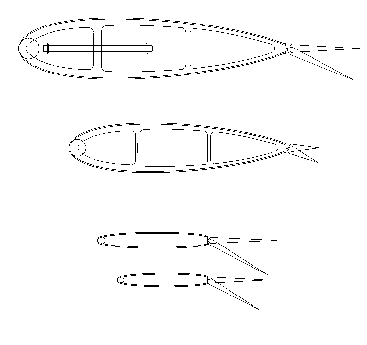
Igor Burger · Dec 06, 2003 07:38 PM

edited#27 source
Here is my airfoil, but I have no idea how you want compare it

I could be better if you can make coordinates, then I can do serious comparison


Dick Fowler · Dec 07, 2003 11:24 AM

#35 source
Borrowing on Serge's post, the formula can be rewritten as:

2W/D+W Where D= Drag and W= Weight

The thing that jumps out here is that we as modelers, don't pay much attention to or have much control over the drag value. If we like the looks we build it.

The effect of weight is far more significant in this formula. Weight is doubled in the numerator and small changes in weight have more effect on the result than similar order of magnitude changes in the drag value. You need more "go" going up and a bunch of "whoa" coming down for a heavier model. It's intuative but this demonstrates why.

So it's obvious that building a "Porker" is detrimental to peformance and it's one variable that is in our control.

Igor Burger · Dec 07, 2003 02:44 PM

#38 source
>>>Since all symmetrical airfoils have the same Cl vs. Alpha curve ….. why do we care about the airfoil section?<<<

Chuck, the problem is they are not linear (sometimes). Just have a look to attached polar. It is real airfoil Wortmann fx 71 with deflected flap. You see the bump on polar. And now imagine, you have to do loop needing lift in middle of that descending part of the bump. You can see there are three distinct AoA giving that lift. I think you will agree that it will be impossible to make round loop.

If you look to my message to Al, the first point is linear response in used segment of lift/alpha polar. I thik this is most important. If you can keep it linear till high AoA, you automatically have lot of lift.

igor


Chuck Smith · Dec 07, 2003 10:19 PM

#44 source
Wow, just got back form the Bills game. Hope I can get my fingers working again.

Igor, you are correct about flaps changing the Cl, but that's only half of the airfoil data. Lift coefficent only gives part of the picture. You need to know the moment coefficent too. Why? Because as you camber the wing, you increase the moment coefficent, and you need to counter that by a downward lifting force on the tail. The lift on the airplane and it's pitching moment are the sum of the wing AND the tail. So, a flapped airfoil for a stunter should be designed to have the lowest moment coefficent possible. This means the tail will have greater pitch authority for tighter corners, and less downforce from the tail increasing the total lift on the airframe. Also, in a quick, abrupt corner, the shed vortex created by the wing is what's driving the increased circualtion, and that's more a function of the trailing edge shape than the rest of the airfoil, but that's a whole different discussion and I'm too cold and an working off some of those $5.00 NFL stadium beers to go there now.

Dick Fowler · Dec 07, 2003 09:34 PM

edited#43 source
OOPS your right shouldn't try to talk to the wife and think at the same time.(She accuses me of this all the time)

Mind if I put some numbers to your comments?

First case At one extreme No Difference or Thrust variation.

(Tu-Td)/Tu = 0

Then 2W/D+W = 0
2W = 0 * (D+W)
W=0

Conclusion - The only way that Tu (thrust up) can equal Td (thrust down) is our model weights nothing. (and Tu >0)

At the other extreme, thrust variation is 100% or Warp 10 up and no thrust down . I’m assuming that we haven’t installed a reversing prop so Td = 0 (Because of this, I think in your number 2 - the trust difference can only be 100% - zero to some value).

(Tu-Td)/Tu = 1

then 2W/D+W = 1
2W = 1*(D+W)
2W = D+W
W=D

Conclusion - At the other extreme drag must equal weight.

These are the two limits

Doing some calculations of drag to weight ratios (D/W)and considering some values in between the two examples above and the two ends.


If there is 0% difference then the condition is W = 0 and if we try to write D/W = 0 then the only possible solution is D = 0 ( very interesting) think we approached a limit here? So with no weight and no drag…. no plane!

Playing with some values:

If there is 10% difference (Tu – Td)/Tu = .1 then 19W = D or W = .052D or D/W = 19

If there is a 20% difference (Tu – Td)/Tu = .2 then 9W = D or W = .111D or D/W = 9

If there is a 100% difference (Tu – Td)/Tu = 1 then W = D or W = D or D/W = 1

All of these gyrations leads me to believe that we can never achieve uniform speed through out all portions of the pattern because of the numbers arrived at using 0% variation. This can only happen with a plane with no mass and no drag!

So if I assume that in the real world that we have an engine tank .etc. etc. that can produces a 5% increase in thrust when we start vertical then

2W/D+W =.05
2W = .05D + .05W
39W = D or W = .025D or D/W = 39

So if I’ve done all the math right I want a plane whose drag is 39 times greater than its weight. YES ???

After thought - maybe the guys building planes with large frontal areas i.e radial type cowls instead of the sleek little 2" spinner jobs know something we don't.

Al Rabe · Dec 07, 2003 11:35 PM

#45 source
I should have known that it would come down to Igor's conclusions that his theoretical analysis of symmetrical airfoils with flaps is unimpeachable and his computer knows all. There is a resolved mathematical explanation to all of the complexities of hanging a flap on the trailing edge of a symmetrical airfoil. and yes, we are still talking about symmetrical airfoils and being shown graphs of the performance of symmetrical airfoils when I have pointed out endlessly that a stunt ship's airfoil is not symmetrical in maneuvers.

Let me offer one FINAL bit of empirical data, subjective though it may be. Years ago I bought a somewhat overweight practice hack. that airplane was very pleasant to fly and was quite competent in all of the maneuvers of the pattern except the lower right corner of the hourglass and triangle. It could hammer a 90 deg corner just fine but clearly stalled in the 120 deg corners. Igor says this should not happen and offers technical reasons why it isn't so. but it happens and I'm sure that many, if not most stunt flyers have experienced this phenomenon. It must have been our imaginations.

I also don't agree with Igor's conclusion that 17% flaps are optimum and I'm sure there is plenty of data to refute this but I am finished arguing with Igor's theoretical software and mathematically defined symmetrical airfoil (with flaps) ordinates.

Al

Serge Krauss · Dec 08, 2003 12:26 AM

#47 source
Hi, Al-

Nice to meet you at this end of the thread. I apparently am enjoying your reparte' with Igor more than either of you is. I'd like it more in a less competitive setting.

If you don't mind my saying so, this reminds me of reading back in my youth about how Moss and Behra and a couple others argued about limiting oversteer at Monza. They lifted, and he put his foot down. Aft weight transfer gave him better rear tire grip, while more throttle seemed to diminish theirs. Different cars, different intermediate goals, different styles, and different data sources, and ultimately differing desires. Maybe one approach was actually better, but who knows? They enjoyed it. I see no real conflict in your approaches. Different, sure, but...What's the problem?!

You (probably) only live once. Enjoy each other!

My few cents worth - you get what you pay for.

Serge (up late and probably should shut up)

Chuck Smith · Dec 08, 2003 06:24 PM

edited#48 source
Al, et. al.,
It's neat how any thread about aifoils always goes to 100 posts and we see lots of graphs and technical discussion, of which I'm guilty.

First though, your methods are completely scientific. You have a theory, and you experiment to test it. That is the very definition of the scientific method. And, I think your method is the best. Let me tell you why.

One point that that bears discussion though, is that in the world of stunt, I think traditional airfoil selection techniques are of questionable value. Why?

When we see a plot of of Cl vs. AoA, it's important to understand how that data was derived. It comes from either wind tunnel, or computer analysis. This is important. In a wind tunnel, you set the section up at a specific AoA, let things stablize, and then get your data. This process is repeated until you have enough data points to make a complete plot. With a computer simulation, this procedure is modeled and the calculations are generally based on something called the "second order vortex panel method"

But in either case, its a steady state analysis and a 2D (no spanwise) flow result. For a "normal" aircraft designer, this data is fine. Using the planform he can make corrections for spanwise flow, and evaluate the section at cruise, climb, descent, and get a basic idea of what the airplanes stall characteristics will be. All of the characteristics of what the plane's selling points such as fuel consumption, cruise speed, approach speed, takeoff perfromance, etc., are based on setting the airplane up in a particular configuration and keeping it there.

The reason this doesn't apply to stunt, IMHO, is that we really don't give diddly about straight and level cruise performance. We want aifoils that can make rapid changes in AoA resulting in manuverability that goes way beyond tradtional evaluation techniques. We are operating in a performance regime that isn't generally worried about for full-size since we are way past the G limits of what a pilot can take.

So, the problem I have with using traditional methods is that we aren't too worried about the steady state. We are worried about what's happening as the wing is CHANGING AoA, and rapidly. Those of you who have had the misfortune of working with sections in a wind tunnel will probably have noticed that when you are changing the AoA with the flow going, there are some nasty transient effects which occur as you change the section AoA. Readings fluctuate, tufts go crazy, and you need to wait a few seconds for them to settle before you take your data. Even when working with the ubiquitous NACA2412 section, you'll notice you need to "finesse" it do get it up to the critical angle of attack. I've even had sections at high AoA's go into a stall because somebody dropped a notebook before I was able to coax slowly up to a higher AoA.

The reason we have the transients are twofold. First, there can be mechanical inputs into the system such as vibration. But the second is of interest to us. When everything else is done, the way an airfoil creates lift, is not by the old "one surface is longer" myth that your high school science teacher told you, but that it imposes a vortex onto the oncoming stream of air. Notice that the computer calculates using a "vortex panel method". There is a votex shed by the TE which sets up the circulation. When we make changes in AoA, a new votex system is shed by the TE. If we go slowly, the flow field can adapt as the vortex is shed and moves downstream, so we stay on the traditional Cl vs. Alpha curve. But, when AoA changes rapidly the section may be changing AoA faster than the flow field can react due to it's mass and viscosity. When this occurs, all the plot data goes out the window until things stabilize.

So let's look at our stunter entering the hourglass. Lots of very fast change in AoA, vibration, turbulence, heck, were even changing the aifoil's shape! I'm sure ther are some really neat studies on transients, but I'll bet nobody has ever studied such large scale dynamic changes. So, thirty or forty years of applied research and evaluation has got to beat the analytical methods in my book.

Brett Buck · Dec 08, 2003 10:56 PM

#53 source

>The reason we have the transients are twofold. First, there
>can be mechanical inputs into the system such as vibration.
>But the second is of interest to us. When everything else is
>done, the way an airfoil creates lift, is not by the old
>"one surface is longer" myth that your high school science
>teacher told you, but that it imposes a vortex onto the
>oncoming stream of air. Notice that the computer calculates
>using a "vortex panel method". There is a votex shed by the
>TE which sets up the circulation. When we make changes in
>AoA, a new votex system is shed by the TE. If we go slowly,
>the flow field can adapt as the vortex is shed and moves
>downstream, so we stay on the traditional Cl vs. Alpha
>curve. But, when AoA changes rapidly the section may be
>changing AoA faster than the flow field can react due to
>it's mass and viscosity. When this occurs, all the plot data
>goes out the window until things stabilize.
>
>So let's look at our stunter entering the hourglass. Lots of
>very fast change in AoA, vibration, turbulence, heck, were
>even changing the aifoil's shape! I'm sure ther are some
>really neat studies on transients, but I'll bet nobody has
>ever studied such large scale dynamic changes. So, thirty or
>forty years of applied research and evaluation has got to
>beat the analytical methods in my book.

This is mentioned in places in various references, but never more than as an aside. I think this is where a lot of problems seem to crop up in comparing analysis to real life. It mentioned it in a previous thread, but a lot of stuff looks great in a static sense, but doesn't really work at all in dynamic situations. And vice-versa.

BTW, Abbott and Von Doenhoff suggest that the max Cl goes up tremendously if the AoA is changing rapidly.

Brett

Igor Burger · Dec 10, 2003 03:28 AM

#65 source
>>>Igor says this should not happen and offers technical reasons why it isn't so. but it happens and I'm sure that many, if not most stunt flyers have experienced this phenomenon. It must have been our imaginations. <<<

No Al, I did not write it DOES NOT happen, I wrote exactly as you write over – SHOULD NOT. May it is my poor English, by I mean it is necessary to do something against stalling in first order. Then we do not need to go to asymmetric airfoil or so. I mean that there certainly ARE models not stalling in last hourglass corner thus I hope you agree – not needing that asymmetry. That is what I mean. I think model, which tend to stall is out of sense, it is for beginners or training flying, and such model is easy to make with more area. The excessive area is not hurting anything on such model.

>>>I also don't agree with Igor's conclusion that 17% flaps are optimum and I'm sure there is plenty of data to refute this but I am finished arguing with Igor's theoretical software and mathematically defined symmetrical airfoil (with flaps) ordinates.<<<

I think this I also did not write deep enough, I wrote about another reasons, not only aerodynamic. Yes you can go even to half a chord with hingeline, you will get lot of lift, but you come to another problems like pitching moment, hinge moment, Netzeband wall problems or structural problems stiffness of wing or flap. I see you are tired from “theoretical software and mathematically defined symmetrical airfoil” so I will show something what you can check yourself with available data:

If you have flap only 10% of chord, it will typically bring extra lift 30 degrees cl=1.4 at 0 AoA and very similar value to the maximal lift.

If you go to 20% flap it will bring cl=1.8. It is only another 0.4 at 2x more area and 2x chord length, so that leads to 3 to 4 times higher hinge moment (that is about stiffness and Netzeband wall). Those are those “another” reasons I mentioned.

If you go to 30% you get only another 0.2 and that is really counter productive in my eyes.


igor

Serge Krauss · Dec 08, 2003 12:00 AM

#46 source

Dick-

An interesting exploration. I've thought over your examples and these are my comments...so far. I hope I'm awake enough to do this!

>First case At one extreme No Difference or Thrust
>variation.
>(Tu-Td)/Tu = 0
> (snip)
>Then W=0

Agreed


>Conclusion - The only way that Tu (thrust up) can equal Td
>(thrust down) is our model weights nothing. (and Tu >0)

However, as the drag approaches infinity, (Tu-Td)/Tu also approaches zero. So infinite drag and zero weight would both be extremes yielding the zero-variation extreme.


>At the other extreme, thrust variation is 100% or Warp 10
>up and no thrust down . I’m assuming that we haven’t
>installed a reversing prop so Td = 0 (Because of this, I
>think in your number 2 - the trust difference can only be
>100% - zero to some value).
>
>(Tu-Td)/Tu = 1
>
>then 2W/D+W = 1
>2W = 1*(D+W)
>2W = D+W
>W=D
>
>Conclusion - At the other extreme drag must equal weight.

Agreed, except I don't think 100% variation is the extreme. If weight approaches infinity or drag approaches zero, there is a 200% difference:

For D = 0, 2W/(D+W) = 2W/W = 2
For W-> infinity, 2W/(D+W) is undefined, but the equivalent expression 2/(D/W + 1) approaches 2/(0 + 1) = 2.


>These are the two limits
>
>Doing some calculations of drag to weight ratios (D/W)and
>considering some values in between the two examples above
>and the two ends.
>
>
>If there is 0% difference then the condition is W = 0
>and if we try to write D/W = 0 then the only possible
>solution is D = 0 ( very interesting) think we approached
>a limit here? So with no weight and no drag…. no plane!

You kind of confused me here. Why did you try for D/W = 0? That would be a condition for maximum variance: 2/(0+1) = 2. This is consonant with Isky's idea that you need drag to minimize thrust differences.


>Playing with some values:
>
>If there is 10% difference (Tu – Td)/Tu = .1 then 19W =
>D or W = .052D or D/W = 19
>
>If there is a 20% difference (Tu – Td)/Tu = .2 then 9W =
>D or W = .111D or D/W = 9
>
>If there is a 100% difference (Tu – Td)/Tu = 1 then W = D
>or W = D or D/W = 1

I agree. These are interesting and reasonable investigations. I'll note that the worst case, with a 200% difference is for D = 0, which at least indicates that, according to this scheme, drag makes a difference, although it alone can't do the job. Playing with various W values in my equation 4 (I think - can't check my post without erasing this!), you can show that the lighter the plane, the more effect drag has - and vice versa. Build a light draggy plane and your up and down speeds will be closest. Of course then you're blown all over the circle by a light breeze!


>All of these gyrations leads me to believe that we can
>never achieve uniform speed through out all portions of the
>pattern because of the numbers arrived at using 0%
>variation. This can only happen with a plane with no mass
>and no drag!

With no mass and no drag, accelerations would be infinite. No mass and a lot of drag would be the way to go, each extreme (zero mass, infinite drag) being sufficient alone to achieve the goal.


>So if I assume that in the real world that we have an engine
>tank .etc. etc. that can produces a 5% increase in thrust
>when we start vertical then
>
>2W/D+W =.05
>2W = .05D + .05W
>39W = D or W = .025D or D/W = 39
>
>So if I’ve done all the math right I want a plane whose drag
>is 39 times greater than its weight. YES ???

Sure looks that way! But we might have the tail wagging the dog a bit here. I think the idea is that with more drag, more thrust will be necessary to fly the plane. Thus your actual excess thrust needed for climb would become a smaller percent of the whole as drag increased. If you reduced weight at the same time, less excess thrust would be needed for climb over dive. So as the equations show, increased drag and decreased weight each diminish the % incremental thrust needed for climb. As each of D and W go in these directions, they help each other diminish the % difference faster. Apparently, however, the amounts of advantage are small with realistic numbers. I'll think further on this. But now I HAVE TO glue the last l.e. half rib over the bellcrank assembly on my plane that coincidentally has a bit of extra wing profile drag, a bit less weight (I hope!) and a bit less induced drag. Yeah, it'll be blown all over the sky. But it IS fun, isn't it...

SK

Iskandar Taib · Dec 08, 2003 11:30 PM

#54 source
Yeah, I think this is something people have been doing for a LONG time (note all those big stunters with the ST .60s and 25% airfoils). I've seen reference to the use of drag to keep constant speed in many, many articles (Casale even added fake air intake scoops on one of this jet-styled stunters for the added drag).

I think it was a lot more important in the past, when people used high pitch, low RPM setups (like the aforementioned ST .60) which weren't capable of varying thrust according to need as the current low pitch high RPM setups do. Back then, Tu-Td tended to be small (since the terms were almost equal), so you relied on airframe drag to keep the speed close to constant instead of relying on the sharp difference in propeller thrust between up and down legs.

Weight has the opposite effect as drag - the more of it you have, the more the airplane wants to decelerate going up and accelerate going down. If you could design an airplane with NO weight, it would 1) require only as much thrust to fly as there is drag at a given airspeed, and 2) there will be NO difference between Tu and Td, so Tu-Td = 0.

Chuck Smith · Dec 08, 2003 07:47 PM

#50 source
Last I heard, Calspan was bought by Raytheon. I was lucky enough to play with the Air Force's F-16 VISTA there. Neat place. Nothing like setting your coffee cup down on the wing of some X-plane. If only those walls could talk... I haven't seen the TIFFS aircraft in a few years. Last time I was in the hangar I saw a cockpit for the TIFFS that looked suspiciously similar to the B2. When I asked about it they responded "what cockpit?" so I dropped the issue 8^).

Chuck Smith · Dec 08, 2003 08:22 PM

#51 source
>Cool observation. How long do you reckon it takes the flow
>to settle down to the static case?
>
>You mentioned the Bills earlier. What became of Calspan?

Good question for which I have a poor answer -it depends. While the vortex should remain stationary in the stream, and therefore move downstream at the airspeed, the vortex may instantaneously cause some flow instabilities which stay "attached" to the airfoil for longer periods. For example, the increased circulation will warp the flow field and cause the incoming air to duck under the leading edge, striking it below the nose of the LE. The air (for reasons that are beyond what we can get into here), instead of moving under the wing- even though it hit below the centerline of the LE, will move forward and around, up, and over the LE, and the sharper curve to the LE may cause the flow to separate as it crosses over the nose of the LE. This can make a fatter airfoil behave like a thin airfoil. Now, how does this separation bubble dissapate? Search me!

But, the long and short of all of this seem to be that it indicates that *maybe* the best stunt airfoil would be thick, and have blunt LE, and a sharp TE. By sharp I mean you put in 64th ply and make a knife edge on it. And that's pretty interesting. In the early 70's a combat ship called the Nemesis appeared which, in a competent pilot's hands, absolutley blew the competition away. It had two features that ditinguished it from the other ships of it's day. First, it had long tail booms, which was an indication that it's designer understood tail volume coefficients, and second, it had an aifoil that had almost cylindrical LE. No matter what the angle of attack, the curve of the LE was fairly constant. What made the Nemesis so deadly was that it could change direction so fast. Hmmmm.......

Howard Rush · Dec 08, 2003 10:43 PM

#52 source
I am familiar with said Nemesis. The airfoil was an NACA 0016.5 with the max thickness squished forward from 30% to 25%.

Iskandar Taib · Dec 09, 2003 03:30 AM

#56 source
If airfoil voodoo takes place in Stunt, there's quite a bit of it in Combat, too. Things I've heard in the past:

This plane turns real tight because the high point is right where the CG is (Tallman Spider construction article).

A good Fast Combat airfoil won't work in Slow Combat (or vice versa) (Various people around the Midwest.).

A "British style" "flat plate" airfoil will never work (as some people told Richard Wilkens).

All those airfoils that are flat behind the high point aren't good for anything (various people).

A regular NACA 4 digit airfoil with an elliptical leading edge has only a fraction of the drag a blunt airfoil has (I think this was one of Barry Baxter's construction articles).

I can point to successful airplanes with NACA foils (Phil Cartier), with blunt foils (Steve Hills designs, Pape's Dawgfighter), with flat aft sections (Phil, more recently), with very thick wings (my own Caudimordax, as published), which used the same wing for Fast and Slow versions (Phil's, Bob Bearden's Fast and Slow Sidewinders), with British "flat plate" airfoils (Wilkens' Blasta)...

While it is true that there ARE bad airfoils (I remember planes I've built with experimental airfoils that had nasty tip stalling tendencies, etc.), I suspect the actual choice of airfoil doesn't really matter all that much, in Combat, if you use a reasonable one.

I was particularly impressed by Steve Hills' blunt foils, as taken from the 1/2-A Sly Sir construction article (the root and tip are different). It turns out to be the same foil used in a variety of other designs used in California and the Pacific Northwest, including John Thompson's Axe. The plane refuses to tip stall even if you set the controls so that the plane staggers around the turn (which you shouldn't do in competition). I've been able to fatten it up, thin it down, etc. just by using scaling tools in drawing programs, and it keeps its flying properties. But I talked to Steve Hills once about how he came by these airfoils, and the answer was pretty enlightening. The general shape's something he'd been using for a long time, while he chose the thickness depending on the size of bladder tube he wanted to use...

John Sunderland · Dec 10, 2003 12:10 AM

#64 source
>>Cool observation. How long do you reckon it takes the flow
>>to settle down to the static case?
>>
>>You mentioned the Bills earlier. What became of Calspan?
>
>Good question for which I have a poor answer -it depends.
>While the vortex should remain stationary in the stream, and
>therefore move downstream at the airspeed, the vortex may
>instantaneously cause some flow instabilities which stay
>"attached" to the airfoil for longer periods. For example,
>the increased circulation will warp the flow field and cause
>the incoming air to duck under the leading edge, striking it
>below the nose of the LE. The air (for reasons that are
>beyond what we can get into here), instead of moving under
>the wing- even though it hit below the centerline of the LE,
>will move forward and around, up, and over the LE, and the
>sharper curve to the LE may cause the flow to separate as it
>crosses over the nose of the LE. This can make a fatter
>airfoil behave like a thin airfoil. Now, how does this
>separation bubble dissapate? Search me

Maybe the question is not how it dissapates but at what thickness it becomes a problem rather than plus.

Chuck Smith · Dec 09, 2003 12:01 PM

#58 source
Igor,
when speaking of drag, you need to remember there two different sources. Remember, we don't really care what the section does in a tunnel. Sure, we can use a pitot to measure the wake velocites and get a drag number, but what does that number mean in the context of an airplane?

On the airplane we need to know the form drag and the induced drag. Seems to me - with a stunter's very light wing loading, in level flight the form drag is most important, since we are at a low Cl for the wing. But when we enter a turn and go to high angles of attack, the induced drag is probably having a much great effect on ship, and induced drag is related more to the planform of the airplane than the airfoil. As I mentioned earlier, the best L/D is when the form drag equals the induced drag.

Iskandar Taib · Dec 09, 2003 09:20 PM

edited#59 source
Right - what we really want is LESS drag in the turns and MORE drag in the straight portions. This is because we want the airplane to fly as close as possible to constant speed. With the old ST .60 type powerplants, thrust is almost constant (little braking on the down lines), so we want a constant amount of drag (at a given airspeed) to balance the (hopefully high) thrust. The best way to get this is to have high profile drag, and low induced drag, since profile drag is constant but induced drag goes up in the turns.

So the thick airfoil, or "smart" airfoil with flaps, is the way to go.

Howard Rush · Dec 09, 2003 11:09 PM

#60 source
There are more airfoils in heaven and earth, Horatio, than are dreamt of in your philosophy.

John Sunderland · Dec 09, 2003 11:48 PM

#63 source
From Als go for broke article I used the 25% equation symetrical but with a round LE and the high point forward as per Teds Imitation series in 81. The original Chevelle was designed to run a 424 with a shorter span and thick section. Its very stable and turns well with out loss of lift. 58 span and 680 squares. I figured the thicker section might hold it back a bit but it really hasnt hurt anything that I can tell over the last seven years.

I also ran a thin high aspect Geobolt wing in the last one. It worked well also.

Dick Fowler · Dec 10, 2003 09:47 AM

#66 source
Back to the original post. I've been playing around with the formula and getting some interesting results.

Considering Tu-Td/Tu = 0 , there are an infinite number of solutions provided that Tu = Td and Tu>0 yet 2W/D+W = 0 is only satisfied when W = 0 or D = infinity (wish I had one of those keys)

The only way Tu can equal Td is if Td is pointed upward. (vector quantities)

Consider Tu-Td/Tu = 0 (Constant engine thrust - No variation or change in thrust from up to down)

Tu = -Td

These are vector and not scalar values so the only way that this condition is true is when the down thrust Td is equal in magnitude and acting in the same direction as Tu.

Tu = -Td

Tu=-(-Td)

Tu = Td

So in order for this condition to be true we must reverse the direction of the thrust at the top of a maneuver by rotating the model to a nose up and tail down attitude, or reverse the prop pitch or engine rotation.

Does this mean we will see helicopters in PA at the next NATS?

Assuming that we stay with our current configurations, next best limit would be a situation where we kill the thrust at the top of the maneuver so that Td = 0. Actually the best solution would be to dial down the thrust as it flies from level up to the top of an overhead maybe along the lines of Available thrust = (Total Thrust) X (Cosine (angle formed between the lines and the ground)) with level defined as zero.

Tu-Td/Tu

Tu - 0/Tu

Tu/Tu = 1

and Tu-Td/Tu = 2W/D+W


2W/D+W = 1

W = D

So under the conditions of no down thrust our best case is drag equal to the weight (Kind of intuitive)

So you ask what does all this mean? ....... I don't know! It's just fun to play with our toys.

Should start a post on weird solutions like:

Employee drag brakes on the "down maneuvers".

Fill our models with hydrogen until we reach neutral buoyancy....Hummmm
Think about this one.

Could use really small motors.

Flying speeds could be slow ... fast enough to finish in time.

If engine quits .... reel it in

Crashes would be really cool ..... explosions, fire and smoke.

That's it ...... Blimps at the NATS. (or the helicopters)

Also thanks to Serge Krauss for his offline (and online) inputs .. very helpful

LeagueCityRalph · Dec 29, 2003 06:45 PM

Whew . . .#67 source
And to imagine that I thought Wild Bill's essays on CLPA aerodynamics in the 1960s American Modeller were exhausting . . .

Jim Pollock · Dec 29, 2003 09:22 PM

RE: Whew . . .#68 source
Ralph,

You must remember that there are a lot of Engineers, Rocket Scientist, Physics and Math professors that get into the mathematical theories and descriptions of what is going on with airfoils. When they are talking back and forth to each other then us mere mortals are really in the dark!

Jim Pollock (A mere mortal )