Stuka Stunt Control Line Forum
Archive, 2000–2021 · recovered from the Internet Archive
Forums › Stuka Stunt Main Forum

Do Venturis Work?

Stuka Stunt Main Forum · 55 of 55 known posts recovered

Howard Rush · Mar 19, 2004 02:53 AM

#0 source
In our quest to make an OS .15 run on a bladder, Preston and I tried making a very efficient venturi with a little hole, so as to provide the greatest possible gradient of pressure drop with RPM while maintaining power. I tried it Saturday, and it didn't work much better than squirting fuel into an open intake.

Then I did some ciphering. I figured that the highest possible flow rate through the intake is .15 cubic inches/rev. If I calculated right, with that flow the pressure drop at the 5/32"-diameter venturi throat was about 0.1 psi. (I don't have the number handy, but it's not much.)

If this is true, our "venturis" just function as flow restrictors that cause a pressure drop downstream. I seek wisdom from you folks who know better than I how venturis work.

LNeumann · Mar 19, 2004 09:06 AM

#1 source
You may be right about the restrictor part of it, Howard.

Now I am curious, however. How did you make this venturi? Was the needle through the middle of the restriction as on the normal OS, or was the needle in a different location? What size restriction did you use on the venturi if you did put the needle in line, and where/how was the fuel inlet? The maximum restriction and fuel inlet should be in the same approximate location. But I am curious as to what size venturi you used, needle, etc.

If the needle passed through the venturi at the location of the maximum restriction, then it was a small venturi, indeed. If the needle was elsewhere, then it was a rather large one.

As to the pressure drop you calculated, I tried once to determine how much difference muffler pressure made to the fuel flow. I took the end of the tube coming from the muffler and inserted it into bottle of water. The bubbles stopped flowing around 4 to 6 inches deep. By rough calculations that would be around half a pound difference, compared to our normal 15 or whatever pounds atmospheric pressure. But that would be pretty huge compared to the pressure draw you calculated on your engine. But I guess that is just another illustration of why we need smaller venturis with smaller engines.

Give us the facts, man, give us the facts. Don't keep us in the dark.

Leonard Neumann

Howard Rush · Mar 20, 2004 03:34 PM

#17 source
I get 0.18 psi for 5 inches of water.

Alan Hahn · Mar 19, 2004 09:37 AM

#2 source
Just one small comment, I agree that if the engine is turned over slowly, the flow will be, on the average, the volume swept out by the piston from the top of the intake port to TDC (less than 0.15 for a 15 engine---right?). On the other hand, this volume (if it really would breathe that well), has to flow only while the intake port is open.

So what I am saying is that you will get a little more velocity because the volume needs to flow over only part of the 360 degree cycle.

I think this is another reason that sub-piston induction is suppose to work (I think). It gives a chance for more air to enter the slightly-sub-atmospheric pressure in the crankcase.

I also know Scott Bair had a few comments about venturi design in his "classic" article on the 2 stroke engine. As I recall, he said the downstream flair of the venturi shouldn't be more than 14 degrees. Something about turbulence and sub-atmospheric crankcase pressure. This is getting out of my region of expertise ( experimental High Energy physics), so I leave it to the "rocket scientists" to respond.

Alan

Howard Rush · Mar 19, 2004 10:11 AM

#3 source
That's an interesting point. If the air goes through there in squirts, the average pressure drop would be greater, because pressure drop is a function of the square of velocity. I didn't measure the pressure. I forgot to put in a pressure tap. Next time I try it, I'll administer fuel through a different hole in the engine and use the existing fuel spigot to measure pressure at the throat (just downstream of the throat, per F4F's advice).

Mike Alimov · Mar 19, 2004 10:27 AM

#4 source
LAST EDITED ON Mar-19-04 AT 10:31 AM (CDT)
 
Howard, while I never tried to calculate the actual pressure drop at the venturi, the number 0.1 psi just seems too low. While with bladder systems you're not concerned about having to draw fuel from a tank, the open-vented (especially uniflow-vented) stunt tanks require lots of suction to pull fuel through ~10 inches of thin tubing and, what's even worse, through the tiny passages in the needle valve. Yet all 2-stroke engines are quite good at it. I believe that even OS.15 is quite capable of working with uniflow tanks.
In your calculations, you based the flow rate on the displacement/rev assumption. While it's a good starting point, there may be some significant correction factors. Displacement reflects amount of gas (fuel mixture) that can fill the cylinder (minus combustion chanmber volume) when piston is at the bottom position (BDC - term?) at ATMOSPHERIC pressure. However, we know that no process inside an internal combustion engine takes place at atmospheric pressure.
In other words, I have a feeling that our engines pack more air/fuel mixture per rev than their nominal displacement. Hence, the flow velocity through the venturi is greater than we think. The higher the velocity, the greater the pressure drop, which explains why the (unpressurized) fuel suction is so good in our little engines. Bigger venturi, less suction. I've proven that to myself. In bladder systems, the venturi is nothing but an air flow restrictor. 4-strokes is another bowl of wax.

P.S. Just posted this and saw Alan's comments; of course, the induction timing is not 360 degrees but less, therefore the velocity is higher yet!

Howard Rush · Mar 19, 2004 11:16 AM

#5 source
Engines with obstructions in the intake suck fuel. We call the obstructions venturis, but I doubt if they are. Your argument assumes that they are and hypothesizes how they might get enough airflow to work. This is a reasonable way to look at it. If the bottom of the hole next to the crankshaft is .333" in diameter, the throat is 5/32" in diameter, and the venturi is 100% efficient (air is at ambient pressure at the bottom of the hole), how fast would the air have to pass through to get 10 inches of water pressure drop?

Howard Rush · Mar 19, 2004 11:48 AM

#6 source
I should add that I think I probably calculated the pressure drop wrong. I'm hoping somebody else will calculate it and tell me the real number.

Mike Alimov · Mar 19, 2004 01:07 PM

#7 source
>Engines with obstructions in the intake suck fuel.
Yes they do. In fact, an obstruction with correct geometry (e.g., OS40FP or DoubleStar40 stock venturi inserts) helps suction by providing a narrow yet streamlined passage where airflow is the fastest and pressure is the lowest. Geometrically bad obstructions (typical RC barrel-style carburator, deflected) create turbulent airflow, chocking the intake area but not helping suction a bit. Hence, need for muffler pressure, Perry pumps, etc.

We call
>the obstructions venturis, but I doubt if they are. Your
>argument assumes that they are and hypothesizes how they
>might get enough airflow to work.
Venturis are not always obstructions. They are in case if they constitute the biggest bottleneck in the overall engine airflow path. That's why our typical "choked" stunt engines can develop more power if we open up ventury (yes, this leads to flatter torque curve -> undesirable run characteristics -> runaways, etc, etc, thus the need for changes in porting and timing to return run under control, but this is not relevant right now, since we're talking .15's on bladders). There will be a point where further increase in the venturi choke area will not result in power increase. I'd say that's where venturi is no longer an obstruction. That is also the point where only bladder may work.


DRINDAK · Mar 19, 2004 01:24 PM

#8 source
In the March/April 1995 issue of Stunt News, Frank Williams wrote a great column about stunt venturis. He presented results of measurements he had made with various venturis and spray bars mounted in a ST 60 case, varying air flow to simulate different engine speeds. He plotted a set of curves of fuel draw versus RPM for four venturis. Based on his measurements, 15 inches of H2O is a reasonable number for fuel draw from a standard stunt venturi. (He got slightly higher numbers, about 18 inches of H2O, using a spigot system).

Adding to Frank's information, I measured the flow losses in some typical fuel tubing and reported the results in one of my Stunt News columns. In a later column I put all the information together to explain the Great Mystery of Stunt -- the two/four break.

Good luck with your OS-15. I'll see you in Muncie.


Yours in Stunt,

Noel

Igor Burger · Mar 19, 2004 02:19 PM

#9 source
>>>If this is true, our "venturis" just function as flow restrictors that cause a pressure drop downstream.<<<

Almost yes. However the exact calculation is relatively difficult. If you assume that the venturi is only pipe of constant bore venting to wider crankcase with larger (not restrictive) diameter, then the pipe is an restrictor which makes pressure drop from atmospheric pressure to minimal pressure just on end of pipe. The calculation depends on RE number, because the resistance is different for laminar and different for turbulent flow. Equations are available on internet, I even saw a page with calculator, but now I am not sure where. I will try to find it somewhere.

So it means that theoretically the pressure should be equivalent on end of restrictor and also under in larger pipe. A friend of mine was very surprised after dismounting of vetury like used on PA’s and Jett’s. That type where the NVA is out of the ventury and where only drilled vent goes via plastic wall with unsealed space between the ventury and the case. If the pressure under the ventury would be higher than pressure in thinnest place of ventury, then the air would leak between the case wall and plastic ventury and it will not load the fuel. But we all know that even those unsealed venturies works well and sealing on top of case is enough.

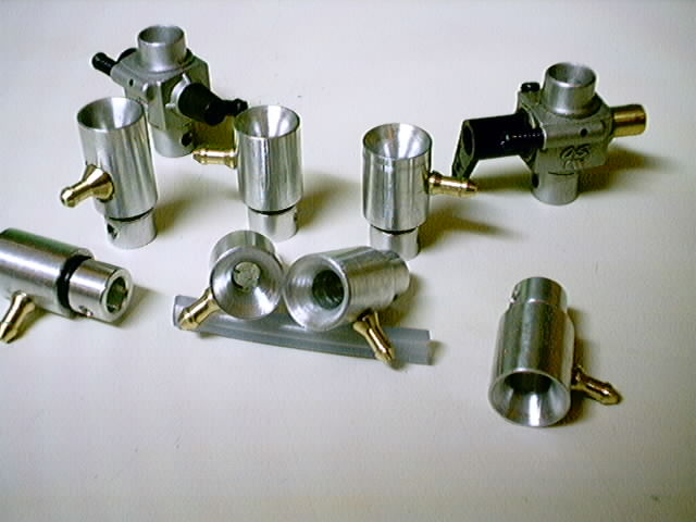
But if there is a spigot or NVA in flow or an edge where the thin pipe converts to wider vent, there is a flow acceleration which also makes LOCAL pressure difference (by Bernoulli) and thus after that edge (down the flow) is little pressure drop. That is why the hole in NVA should be oriented just little bit under the thinnest place, or why those old T/R venturies (on picture) have holes just under the edge past the thinnest place.


Igor Burger · Mar 20, 2004 09:19 AM

#13 source
Here is a calculator and some math about pipe flow friction:

http://www.efunda.com/formulae/fluids/calc_pipe_friction.cfm

it counts and limits number of calculations, so I think it will be good idea to disable cookies before it asks for money

Howard Rush · Mar 20, 2004 06:54 PM

#19 source
Thanks, Igor. According to that venturi calculator, to get 10 inches of water pressure drop would take 56 cubic inches/second flow. .15 cubic inch per rev at 12KRPM is 30 cubic inches/second. That flow rate should give 3 inches of water = .1 psi pressure drop (my calculation-- the Web site asked me for money after the first two calculations). Gradient of pressure with RPM is .02 psi per thousand RPM.

I don't think it's the venturi effect that regulates fuel flow.

Bob Reeves · Mar 19, 2004 06:56 PM

#10 source
Great thread and probably a good time to bring up a few more questions/observations.

Lately I have been playing with making a few venturies for a couple of different engines, Super Tiger 46, Stalker 61. Having no idea what I am doing I have been analyzing and measuring as many stock and after market venturies as I could get my hands on. The net result of all this research is I am more confused than I was when I started. Here are a few of my observations.

Seems as though the Stock ST 46 and G21 35 venturies are the same size <>.159.
Found one Stock ST 46 sprinkler that the holes are not at the narrowest part of the lower taper. This one has the holes just above where the taper starts.

Some venturies, Stock Stalker and aftermarket Tigres have no lower taper in the normal "Venturi" sense. They have a straight passage with a relieved bottom end that flairs rather abruptly. Kinda like a countersink was used just to open up the bottom end.

I was told that one fan of the Stalkers over in the UK makes new venturies without the countersunk bottom because it gives him better fuel draw.

All of this makes me wonder...

Does a spigot venturi need to be tapered at the bottom to perform properly?
Does it really make any difference if the venturi is shaped like a real "Venturi" or if it is just a straight hole?
On the Stalker, if the venturies are the same size why would eliminating the flair at the bottom increase fuel draw?
Should we be flaring the bottom of home made venturies or just leave the straight hole.

This also makes one think that the restrictor theory is right-on and just about anything will work.

Gary Weaver · Mar 19, 2004 09:41 PM

#11 source
LAST EDITED ON Mar-19-04 AT 09:58 PM (CDT)
 
When running a bladder the engine does not care if it has venturi suction or not like it would when the engine has to suck fuel from a fuel tank. I make all my own venturi for my OS 25 engines. I have tried all sorts of things and they all still work. Many of my homemade venturi will NOT work with a fuel tank but work fine with a bladder. I cut a piece of 1/2" diameter aluminum rod 1" long then drill a 3/16" hole down the center. I turn the end of the aluminum rod to fit the hole where the RC carburator use to be. I drill a .120" diameter hole in one side of the aluminum venturi and press in a 3/4" long piece of 1/8" brass hobby tubing just far enough so it comes to the tip edge of the 3/16" hole. I don't want the brass tubing pushed in too far because I don't want it sticking out inside the 3/16" venturi hole. This venturi works fine with a bladder but will not work with a fuel tank unless you are using muffle pressure.
I am not sure what type needle valve the OS 15 has. Some needle valves will not work with a bladder because they can not screw in far enough to restrict the flow of fuel. A fox engine with the needle valve that has 2 flat places on the tip end will not work with a bladder. Try this experement and see what happens, screw your needle valve in all the way then release the fuel line clamp to see if fuel flows into the venturi. If it does then your needle is the problem. Fuel should stop or be restricted to almost nothing. Screw the needle out 1/2 turn, prime the engine with fuel, start the engine and once the engine comes up to speed release the fuel line clamp. If the engine runs lean an dies turn the needle out a few clicks. If the engine runs rich turn the needle in. Here is a pic of some of my first verturi I don't got to this much trouble any more a piece of aluminum with a piece of brass tubing stick in the side work great. The diameter of the hole drilled through the venturi is important. If you drill the hole in the aluminum venturi too large the engine won't run. I am guessing a venturi hole for a size 15 engine should be about .150" diameter maybe smaller. The hole that you drill through the venturi has to be sized for the engine. Its sorta like putting a car type carburator on a lawn mower engine. The hole diameter that is drilled through the center of the venturi is some what important but not real important. If the hole is too small the engine will not get enough air with the fuel to run at full power. If the hole is too large the engine does not care because it is not sucking in fuel it is only sucking in air the fuel comes in on its own under pressure from the bladder.

Gary Weaver [email protected]

Charlie Chan · Mar 19, 2004 11:01 PM

#12 source
If you make your venturi small enoughand turn enough Rpm you can lower your compression ratio.
If you don,t beleive this, you probably didn,t get past the 600
rev. in a top fueler run.
The answer to lowering the comp. ratio is Volumetric efficency
at a high enough rpm with a small venturi the vent. will not flow
as much per stroke therefore doing the same thing as lowering the
compression ratio.
Just somthing to think about.
I find carbs and venturis in engines very close to black magic.

Charlie Pate

Ion Muniz · Mar 20, 2004 09:57 AM

#14 source

>I find carbs and venturis in engines very close to black
>magic.

I sometimes get the same feeling with computers.

When I was teaching at the jazz department of the Sibelius Akatemia, in Helsinki (around 1989-90) I made a book about improvisation patterns.

The whole university was running on macinstosh 'puters, and the head of the computer department (or whatever you call it), a Finn called Hannu Apajalahti was having a hard time with those LaserWriters.

At some point I sugested that the university could hire an african which doctor and have him available when those crazy problems came up.

I reasoned that it would be a LOT cheaper than them apple technicians.

And Hannu, for a couple of seconds, even considererd my sugestion!!!

Ion Muniz

Ion Muniz · Mar 20, 2004 10:00 AM

#15 source
just open up the venturi and use a .10 NVA. Use a remote one.

Ion

Howard Rush · Mar 20, 2004 12:20 PM

#16 source
LAST EDITED ON Mar-20-04 AT 12:26 PM (CDT)
 
Well, that's what we thought. You can see OS .10 NVAs and Steve Helmick's lovely, wide-open intakes on the November-December, 2000 Stunt News front cover. That system used crankcase pressure as a reference pressure for the regulator. Crankcase pressure decreases as RPM increases. If the engine is running rich and slows down, it gets an even higher fuel flow. Thus it quits. The engine-fuel system is unstable when the engine is running rich. This has been a problem. We wanted a stable system that wouldn't cause the engines to quit at inopportune times, such as during overhead eights.

I thought that a venturi would draw more fuel as RPM increases. It would be nice to have no power loss through the venturi. Therefore we made a nice, long venturi with a 7-degree divergent section and used a constant-pressure reference for the regulator. It didn't enable the engine to run rich stably. I then calculated that, sho nuff, the theoretical pressure drop through a venturi is small. If I calculated correctly, we'd have to put something in the intake that obstructs the flow to get the engine to draw fuel. This will cause a low pressure at the crankshaft face. Thus, we'll have to accept some power loss to get the requisite fuel flow increase with RPM. Before I give up on real venturis, though, I would like somebody else to calculate the pressure drop for the case above, so I can see whether I'm full of bosta (to borrow from another thread).

I might do some more experimenting if it's easy.

ferocious · Mar 21, 2004 06:53 PM

#26 source
use a Cline fuel valve and a hard tank.
\
or set up the regulator to use atmospheric pressure as a reference.(i.e. a Cline fuel valve)

or try a mechanical governor- more rpm=more fuel flow, lower rmp=less fuel. Would be a bear to regulate and maintain though.

If you are trying to run a bladder, what was wrong with the setup Paul Walker used on the B-17. He seemed to have pretty good success.

Or just run the motors like a combat plane- wide open, and regulate the power and rpm by restricting the timing on the motor. If you run a relatively small, low load prop and let the motor run in a two cycle they will run pretty good. You'd have to build or carve some 7/1.5 props though.

Phil C

Howard Rush · Mar 22, 2004 01:34 PM

#32 source
"use a Cline fuel valve and a hard tank."

Too heavy, other constraints (It's a long story)

"or set up the regulator to use atmospheric pressure as a reference.(i.e. a Cline fuel valve)"

Thanks. I'll try that with the McFadden regulator. The Cline is too heavy.

"or try a mechanical governor- more rpm=more fuel flow, lower rmp=less fuel. Would be a bear to regulate and maintain though."

I can't figure out how to do this.

"If you are trying to run a bladder, what was wrong with the setup Paul Walker used on the B-17. He seemed to have pretty good success."

I'm trying to make something that works better. Paul was influenced by some old combat flyer who doesn't know what he's doing.

"Or just run the motors like a combat plane- wide open, and regulate the power and rpm by restricting the timing on the motor. If you run a relatively small, low load prop and let the motor run in a two cycle they will run pretty good. You'd have to build or carve some 7/1.5 props though."

Well, you'd think so. This particular application has RPM constraints. Among the constraints is that an APC 9-4 depitched to 3.25" hits an RPM where there's a structural resonance. An APC 9-4 is the smallest load we can use.

ferocious · Mar 23, 2004 09:23 PM

#41 source

>Well, you'd think so. This particular application has RPM
>constraints. Among the constraints is that an APC 9-4
>depitched to 3.25" hits an RPM where there's a structural
>resonance. An APC 9-4 is the smallest load we can use.

Laminate some carbon fiber on the outside of the fuse. It shouldn't be that hard to stiffen the fuse and avoid the resonance. That might be easier than trying to go to fancy regulators.

Phil C

Howard Rush · Mar 23, 2004 09:50 PM

#42 source
Thanks, Phil. Where do you get carbon fiber?

Igor Burger · Mar 20, 2004 06:02 PM

#18 source
This thread inspired me to learn more about pipelines, the dynamics, the friction inside and so. I got some books, I got lot of info, but it looks more complex than I expected … terrible … however I have some thoughts (not proofed, do not take this like facts, it is all only my hypothesis, I did not proof anything, just take it as food for thinking, and if someone see a mistake or new idea or proofed fact please put it here):

We have two streams (fuel in fuel tubing and air in venturi). They are in two separate restrictive pipes and they have equivalent pressure on their ends where they are connected. We force the air stream to keep velocity relative to rpm (means volumes per minute). Higher velocity in venturi makes lower pressure on end and thus higher velocity also in fuel tubing. The restrictions in both pipes are the same physical effects and if they are both linear, if the pressure on both begins of both pipes are equivalent (atmospheric) the mixture must be independent of venturi air velocity.

That is the model, and now we have several exceptions which can affect that rule:

1/ As far as I understand whole thing, the pressure drop in pipe is linear to velocity if the flow is laminar, but it grows with square of velocity in turbulent flow. This can change the mixture if one of pipes goes to turbulent flow earlier than other. I really do not know which and when goes to turbulent, as it is not simple pipe, it is pipe with restriction on one place (either needle in NVA for fuel either NVA or narrowest place in venturi). It will need careful analyze of RE numbers inside, but I would guess that the fuel pipe is laminar, as the restriction in NVA (the needle) is very short and velocity low. So if the venturi flow is also laminar, then we have constant mixture. If the airflow gets turbulent early enough, then the growing airflow will make higher pressure drop than restrictriction in NVA and thus the mixture at higher rpm can be richer. It is because if engine loads twice more air, the pressure drop is 4 x higher (quadratic) and that 4 x higher power drop loads 4 x more fuel (linear) what makes 2 x richer mixture.

If we want improve (or secure) that effect, it will need to keep laminar flow in fuel – means thick tubing (low velocity), usage of filter (kills turbulence if it wants to propagate), avoid any shaking of tubing … and on opposite side to make turbulent flow via rough and long venturi, but also all “aerodynamic” tricks improving draw like “venturi shaped” venturi, NVA in stream, inlets at edge, fuel posts to place with higher velocity or those mentioned by Bob, they have all quadratic response to velocity.

2/ Muffler pressure has exactly the same function like venturi flow. The volume and velocity depends on velocity in venturi and thus it depends on RE number at outlet. The only real effect is, that it makes the system less sensitive to changes in head pressure in fuel.

3/ Constant pressure in fuel causes some additional fuel flow component, which does not depend on air velocity in venturi. So if the pressure in fuel is higher than air pressure, the mixture is richer at low rpm and leaner at high rpm. This is what we do not want and this is also case of bladder. But lower head pressure like uniflow air vent on right side (bottom down the centrifugal force) of tank makes richer mixture at higher rpm and leaner at low rpm.

4/ At last one note, the engine needs at higher rpm leaner mixture, means that also if we keep constant mixture, and we unload the engine to higher rpm, it gets rich.


Gary Weaver · Mar 20, 2004 09:40 PM

#20 source
I have never tried to do the math on this the numbers are so small I figured measurements and math would not be accurate anyway. The true story is told by the engine itself and how much power and RPM's it will acturally produce. I made 10 venturi then I went flying with a good selection of props. I did about 20 test flights to see what worked, what didn't work so well and what worked best. As it turned out for me a venturi hole about 10% larger to 20% larger than the RC carburator was best. If the hole gets too large it makes the engine hard to start. If the hole is too small the engine is low on power. I know velocity increases as the hole gets smaller, the amount of fuel and air in the crankcase is less because the engine is sucking a vaccuum on the venturi. If the venturi gets too large the air velocity is low and slow air flow has a hard time moving the fuel to the engine. The only math I did was to calculate the area of the RC carburator hole minus the spray bar area. I made a venturi to match the same area. I made several other venturi with 5%, 10%, 15%, 20% 25% 30% larger and 5%, 10%, 15%, smaller and tested them all. 10% to 20% works best for me the exact % depends on the condition of the engine.

Gary Weaver [email protected]

mogren · Mar 20, 2004 09:55 PM

#21 source
I often bench run RC engines with the carbs out. No venturi at all, no carb, just a hole into the crank. i use a high mounted tank and a remote NVA. The RPM is about as good as it can get. The fuel burn is very high due to "fuel stand off". Add a venturi and the rpm stays the same but the fuel burn rate drops inrelation to the actual power output. We often run the Thunder tiger 15 with no venturi this way on combat stuff to pick up a few revs. 2oz goes real fast(2min).add venturi and 2oz goes 4or 5min. just like bench test.
When I draw the(theory) NV position for a 2 hole NV. I figure the highest and the lowest pressure will be, just on the 80* angle and the 120* angle. The fuel draw is the highest this way in test. twist the NVA until the engine run is the richest.
venturi effect... Needs some " stack up"" of incoming air, to increase the speed in a narrow area of the intake, just past the narrow point. If you could figure the intake quantity of air for each rev and try to have an intake tube volume this size X 1.5, maybe the added restriction might be paid back by a better crank charge velocity.
In my mind, the most effective "venturi", will need to be a certain distance above the crank hole, with a large "bump" on the inside radius,aimed towards the back of the crank. the outside would need to be smooth, with no restriction . This "could" , in conjuntion with optimal length of tube above the curve, add crackcase filling. IF. the port timing, compression, prop, and fuel were all optimized at the same RPM. You measure the correct distance(of the pinch) above the crank hole by measureing the case pressure and the intake suction. the case pressure would come up a tad at the best combination, intake stays the same. If case pressure comes up any, RPM should also. IMHO, of course, YMMV. Mike Ogren

mogren · Mar 20, 2004 10:08 PM

#22 source
Howard, Try a 1/8" tube facing the exhaust port(for regulator reference). File an angle on it and drill the case next to the port. This may give a closer relation to RPM than case pressure. If the tube is close to the port,it should vary more than the end of the muffler.

Howard Rush · Mar 20, 2004 10:28 PM

#24 source
I'll try that. Thanks.

Howard Rush · Mar 20, 2004 10:24 PM

#23 source
"...if the pressure on both begins of both pipes are equivalent (atmospheric) the mixture must be independent of venturi air velocity."

So the pressure out of the regulator should be as close to atmospheric as possible. The spigot that puts fuel into the venturi was made from small hypodermic-needle tubing. It had so much restriction that it required 150 mm of Hg (about 3 psi) to get enough fuel to the engine with the needle valve wide open. That would overwhelm the (maximum) 0.1 psi venturi drop. I guess I could try a bigger spigot and a regulator output pressure close to atmospheric. Hmm, this is approximately what Paul Walker used in his first B-17.

Igor Burger · Mar 21, 2004 08:05 AM

#25 source
>>>as close to atmospheric as possible<<< or even less than atmospheric, it will make better "self regulation" in engine because of richer mixture at higher rpm

F4FGuy · Mar 21, 2004 07:17 PM

#27 source
Ron B.
F4Fguy


Howard:

When I suggested you use hypo tubing I was referring to the pressure measurement,not fuel supply.The idea is to lessen the effect of the pressure measurement tap on the measurement itself.The smaller tube also is more sensitive due to lower inertia in the system.when using the hypo for fuel you restrict flow,as you discovered.For pressure measurement you have (essentially) no flow.

That said,a few thoughts,in no particular order.I believe a large part of the problem is that you're dealing with pulsating,not steady flow.The inlet valve is open only part of the time,usually on the order of 140deg. crank angle.All the air has to be injested during that time,including accel/decel time.The pressure differential is going to go from 0 to peak and back to 0(excluding inertia effects)in that period.You're probably going to have,as you've already seen,great difficulty detecting the peak differential.If you have access to some low pressure high response piezo or other electronic pickups you might have more success.

All the above assumes(always bad)that the flow is reasonably coherent.Turbulence can,and will,change the absolutes but,the basic effects will always follow the same trends.

Also,remember that no engine ,let alone our little two stroke monsters,has 100% volumetric efficiency.I'd guess a number like 50-60%would be more like it.

As to the idea of a restrictor;Bosh,Sir!Nonsense Sir!Not spot on!A reasonably designed venturi has almost 90%recovery,a good one well over that.The pressure drop is ALWAYS giong to be closely related to the difference in diameters of the run and the choke.Just because you haven't the means to measure it doesn't mean it's not there.

You have said that the result of testing the "good" venturi wasn't "much better" than the open pipe(did I get that right?).This would seem to say that there was some improvement.True?If so,how much?

The bladder/regulator:

I wouldn't be surprised to find the regulator problem related to the pulsation.The inertia in the mechanics is not likely to be low enough to follow and respond in real time to the peak pressure differentials.
Setting the pressure to atmospheric,it seems to me,is kind of defeating the purpose of the exercise.

If you have 150 PSI fuel pressure available,have you given any thought to direct injection?By setting the injector at a known distance from the top of the stroke,you can set basic injector timing,using the piston as a control valve.Fuel pressure can then be used to fine tune for the desired conditions.Either aircraft speed or engine speed,or both could be used as references.

Sorry for the rather disorganized form,but those are my thoughts at present.

Regards,

Ron B.

Howard Rush · Mar 21, 2004 10:58 PM

#29 source
Thank you. I was hoping to hear from you.

No, I can't blame you for the small supply tubing.

I haven't measured pressure at the venturi throat. I'm almost convinced that there's not much reason to do so. The venturi didn't allow the engine to run at a stable, rich setting. Maybe it was better than the wide-open intake with crankcase pressure as the regulator reference, but it wasn't dramatically better. Then I did the calculation, which I interpret as telling me why the venturi didn't do much.

The pulsing effect should give more average pressure drop than if it's steady flow, but I'd be surprised if it makes up for the amount less than .15 cubic inch of air that actually flows through the intake per rev. I presume that's what you mean by volumetric efficiency. I would reckon to get the most benefit from the pulsing, you'd have a very short venturi, which wouldn't be as efficient as I hoped for. Indeed, that's pretty standard stunt practice.

The regulator works just fine, as far as I can tell. The point of having a low regulator reference pressure is to get a low regulator output fuel pressure. If the output, hence the supply pressure to the needle valve is low, flow rate to the engine might be influenced by the gradient of venturi pressure drop with RPM, but I'm pretty much convinced that any intake that adequately regulates fuel flow will cost power.

I'd be the first person to do something electronic, but I would be forbidden to add more than 5 grams per engine or decrease the system reliability.

Change of subject: Got any ideas for a reliable, 3-psi pressure reducer?

F4FGuy · Mar 22, 2004 11:56 AM

#31 source
>Thank you. I was hoping to hear from you.
>
>No, I can't blame you for the small supply tubing.
>
>I haven't measured pressure at the venturi throat. I'm
>almost convinced that there's not much reason to do so. The
>venturi didn't allow the engine to run at a stable, rich
>setting. Maybe it was better than the wide-open intake with
>crankcase pressure as the regulator reference, but it wasn't
>dramatically better. Then I did the calculation, which I
>interpret as telling me why the venturi didn't do much.
>
>The pulsing effect should give more average pressure drop
>than if it's steady flow, but I'd be surprised if it makes
>up for the amount less than .15 cubic inch of air that
>actually flows through the intake per rev. I presume that's
>what you mean by volumetric efficiency. I would reckon to
>get the most benefit from the pulsing, you'd have a very
>short venturi, which wouldn't be as efficient as I hoped
>for. Indeed, that's pretty standard stunt practice.
>
>The regulator works just fine, as far as I can tell. The
>point of having a low regulator reference pressure is to get
>a low regulator output fuel pressure. If the output, hence
>the supply pressure to the needle valve is low, flow rate to
>the engine might be influenced by the gradient of venturi
>pressure drop with RPM, but I'm pretty much convinced that
>any intake that adequately regulates fuel flow will cost
>power.
>
>I'd be the first person to do something electronic, but I
>would be forbidden to add more than 5 grams per engine or
>decrease the system reliability.
>
>Change of subject: Got any ideas for a reliable, 3-psi
>pressure reducer?

Ron B.
F4Fguy

Howard:

The old Jim Walker regulator which was supplied with his bladder tank was atmospheric referenced.If memory serves,it was light and reliable.I still have one you can have if you want it.It's damaged(one of the fittings is missing)but,the regulator looks easy to duplicate.

I've been mulling my remarks re the venturi.I may have overstated my position re restriction vs "true" venturi.I stand by everything I said about the true venturi,but all bets are off when you bung a spray-bar through it.As I originally said,a good venturi has better than 90% recovery downstream.This depends on having good flow characteristics,as near as possible to true laminar.With a spray-bar ,I seriously doubt you can even approach this.In fact I'd bet the farm that flow is entirely turbulent.This is going to cause massive flow losses downstream.I think Mogren has it about right(post#23)if I read him correctly.You can run a very large bore with a large reduction at the throat if you don't disturb the flow.This explains the differences which are reported between the so called true venturi and a conventional spray bar in a venturi.The venturi effect is completely blanked by the disruption caused by the spray-bar and very little recovery is possible.A post would be somewhat better IF, as you've intuited,the size is very small re the throat.I'd still bet the "sprinkler" is the most efficient of the bunch,again with an IF,if the holes are properly sized ,and configured.By that I mean the holes absolutely must have sharp exit edges,and well rounded entries.This "Borda" exit gives full flow and produces a jet stream(no vapor trails though)which will push the fluid through the boundary layer.Any rounding or irregularity at the exit will allow a Coanda flow which attaches the flow to the inner wall,giving poor mixing and reduced flow.I must say,most of the sprinklers I've seen don't meet these criteria.Generally the jets are too large and most have carefully deburred(rounded)exits.

I guess what I'm trying to say is;there's more to it than simply deducting the area of the spray-bar from the throat area.With a good venturi and good fuel jet control,you should be able to run a very much smaller throat with the same basic bore without any power loss re the spray-bar.The down side of all this is the required length to make it work.The longer the intake tract,the more inertia in the stream.meaning response will suffer to some extent.This is one of the reasons FOX 35s respond so well to load changes(you have NO idea how it hurts me to say that),the intake tract is so short,inertia is minimised.You could also encounter some undesirable harmonics with the longer tract which would throw the whole thing into a true tuning problem(on the other hand this could be used to advantage if you can get it to break back and forth with RPM changes).

Also,if the venturi didn't work,neither would the "sprinkler".The TIGRE 35 and 46 are proof that it can work.I still believe you're simply not working with the peak flows,or the reduction is not sufficient.Remember that,in addition to the reduced flow time afforded by the crank port,you also have a delay due to inertia in the incoming air column which further shortens the time available to come to peak.

Questions before I close:Where are you sensing pressure now?
Why not compare throat and upstream as a reference?This is how venturi flow meters work.

OH!Incidentally,I just realized you said 150 INCHES,not pounds.Sorry about that.

Ron B.

Howard Rush · Mar 22, 2004 01:55 PM

#33 source
LAST EDITED ON Mar-22-04 AT 02:34 PM (CDT)
 
Thanks for the regulator offer. I might take you up on it eventually. I'll try some other stuff first.

Had I done the calculation first, I wouldn't have made the venturi. I'm pretty much convinced that even an ideal venturi wouldn't provide enough delta pressure unless the throat is extremely small.

It's no trick to make an intake that can draw fuel and regulate fuel flow, but not without power loss relative to a wide-open intake. I wouldn't trade much power for rich-running stability. As I remember, the Supertigre had more power with a wide-open venturi than it did with the sprinkler.

I've been using a genuine pen bladder as a pressure reference. The regulator requires a reference pressure somewhere between the fuel-delivery pressure (atmospheric, or close to it) and the supply pressure (8-15 psi). The reference pressure was 150 mm of mercury.

Igor Burger · Mar 22, 2004 10:18 AM

#30 source

The “restrictor” or the “venturi” is a device based on the same physical phenomenon – conversion of pressure energy to kinetic energy and back. Bernoulli says that if you have a liquid (or a gas) of some pressure and some kinetic energy (velocity) and you want to change that velocity (in venturi or restrictor) – means permanently accelerate its mass, you need some pressure difference accelerating that volume, while the conversion conservates the total amount of internal energy. It means if you slow down that accelerated stream back to its original speed after the narrowest place, the accelerated mass must decelerate and thanx its mass inertia convert its kinetic energy back to pressure (counter pressure against that stream).

So far for Bernoulli and his equation, which works ONLY under its conditions, and those conditions, are, that the energy is really constant.

The problem is, that if we accelerate the stream to some velocity, then the stream loses its internal energy because of friction in air, because of thermal conduction in system and may be also some evaporating/condensing thermal effects. However the result is, that in that high velocity, but narrow vent we lose lot of energy and the pressure after slowing down is much lower than expected from “venturi” (read Bernoulli) effect of barking by higher pressure. Instead of pressure we have friction, which lowers that necessary counter pressure.

So I think you cannot say that the “restrictor” or the “venturi” is what makes the suction, it is the same phenomenon, the same energy conversion, the only question is, how efficient that energy conversion is – it is certainly not 0% and certainly not 100% … and that value says how big is the pressure past the narrowest place – means – how efficient the venturi is – means - if it is more “restrictor” or more “venturi”. And that percentage depends on requested suction in fuel line – more suction -> higher velocity -> more loses -> worse efficiency -> more restrictive result that is whole trick and very known from real life I think.

Howard Rush · Mar 22, 2004 01:57 PM

#34 source
If I can't get my pressure back, I'll take my business elsewhere.

Gary Weaver · Mar 21, 2004 10:43 PM

#28 source
LAST EDITED ON Mar-22-04 AT 03:03 PM (CDT)
 
I checked the venturi in my OS Max 25 FX it is .260 diameter. I am not sure how close that is to what other people are using. The airplane flies 75 mph with the 8x6 prop. The engine will turn a 9x6 or 10x6 prop too. I was suprise to see this engine would actually turn a 10x6 prop.

Gary Weaver [email protected]

Howard Rush · Mar 22, 2004 01:59 PM

#35 source
That's a heap of prop for a little engine. I was surprised that the .15 would turn a 9-5. It does so reluctantly.

Lou Crane · Mar 22, 2004 04:16 PM

#36 source
Howard,
You've had a lot of excellent comments on this one!

Time for some brute-force, stone-ax simplification?

For one -- and I expect comments on this -- load changes in different flight attitudes and conditions affect ignition mode. A constant fuel feed will not change that.(Let that just sit there for now...)

Two, we can still consider a spraybar/choke system as an irregular venturii form. "Ideal" velocity would be at 100% Vol Eff, or whatever fraction we presume. Also, consider the accel-/decelerations to cover about 180º shaft period. (Momentum continues inflow across the minimum area briefly after the shaft port closes completely, just as beginning of flow lags behind actual port opening.)

Three, for a "figure of merit" kind of SWAG, think RMS (Root Mean Square -- the presumed mean value of a Sine-wave variation). Average rate of flow would be your Vol Eff number fraction of displacement at twice the RPM. ...or any other way to set things so that the presumed volume fill occurs in half a turn of the shaft. We have real numbers: RPM, Vol Eff(presumed), and displacement. So, the average rate of flow during port-open can be SWAG'ed. We can also SWAG peak flow velocity using the RMS idea. If average is peak OVER 2^0.5, peak is average TIMES 2^0.5.

Crude as this is, ignoring refinements, mass and viscosity matters, it allows picking numbers for a spraybar/choke pairs for similar operation in different sized engines, or finding a clean-bore venturii inner diameter actually matching a spraybar-choke set.

Finally, presumed peak flow velocities can easily approach high MACH Nr fractions, where 'drag' increases much more quickly. If I recall from an XLS I did on this, using Bernouli's Eq, a Fox 35 @ ~10,000RPM has a presumed peak V of about 475'/sec, and roughly 3psi pressure drop at mean velocity through the min area section (choke ID less 0.125 spraybar masked area.) I have had good results cutting chokes to convert RC engines with this simple method...

On the 'restrictor' idea -- A spraybar/choke setup can operate in a reduced mean pressure plenum (i.e., a relatively large volume to damp pulses and extraneous velocity effects) if the inlet net area is less than choke less spraybar-masked area. I did this with an engine I was playing with for fuel endurance. The engine spit too much raw fuel out on the port closure rebound pulse, NOT a fuel-economy good thing. Fox 15BB with a wood plug in the venturii top, drilled smaller than fuel jet zone net area... Significant gain in time per fl oz.

\BEST\LOU

preston · Mar 22, 2004 04:25 PM

#37 source
>>Significant gain in time per fl oz.

If the fuel economy improves, do we get to use
some of the weight savings?

Preston

Lou Crane · Mar 23, 2004 03:43 PM

#39 source
Ron,

The economy experiment was with a shot at CL endurance record in mind.

Power is the last thing needed, here. Consistent run over long times is more important. This Fox15BB, w/Davis diesel conversion, once flew over 45 minutes on about half of a four fl oz tank. (Two dust devils and a brief rain shower while it was up!)(Open record is over two hours...)

To get even more time/oz, nasty things were done to:
Bypass volumes -- (balsa packing to reduce drastically/ keep velocity, swirl, turbulence up for better burn.)

Inlet area -- as mentioned. Hole was about 1/16" ID.

Prop for the .15 was about 11 by mucho pitch: RPM <7K.

"Short" tank run result was from needing plenty of nose-high attitude to sustain flight at ~8+ sec/lap on a symmetrical airfoil. Slow speed exaggerated nose out yaw. Fuel stacked in front corner and below height-centered fuel pickup: I could only get to half of it.

I also learned that knees start to complain after about a half hour. May push through to an attempt one day. (A DDD'ed OS10 benched at a rate of about 60 min/oz at ~3K on a 12-8 shaved paper thin, with even more severe restrictions to air/fuel passages. E.g., plate over exhaust with a 1/16 diameter on top of all the other things...)

Anyone interested in endurance had better have friends who think watching paint dry is so stimulating that they risk a coronary. Also, the model must have a lifting airfoil, or my nose-high, wide yaw experience will be a real problem. Max fuel load for this category is 4 fl oz, btw.

\BEST\LOU

Howard Rush · Mar 22, 2004 07:40 PM

#38 source
You and Ron are convincing me that the venturi effect is actually drawing fuel. It's not unreasonable to assume that all the air goes into the intake in one brief gust each time the shaft goes around. If the gust is a pulse 1/10 of a rev wide and half the engine's displacement of air goes in every rev, that's an average pressure drop of 2.5 times what than I calculated, and a peak of 25 times as much. I wonder how much the pulses get attenuated as venturi length increases. I'll do some more experiments. Thanks, guys.

Lou Crane · Mar 23, 2004 03:53 PM

#40 source
Howard,

Your estimate of about 1/10th of a turn may be effectively equal to the overall result, but I prefer to think of it as acting more like a gradual-lift cam.

There's inertia against the start of flow into the case, and in that region of crank position, the pressure drop is also mild. These probably come near matching, at good, higher velocities, around half-stroke on the way up. The shaft port does not slam open or closed; the area profile varies as the port window wipes across the case opening. Momentum of the incoming charge DOES stack up against the closed shaft port. And its mass does rebound -- it isn't quite like sound wave frequencies superimposed on the motion of the air/fuel mass.

Things like that lead me to think that RMS thing. Bernoulli's Equation relates pressure inversely as the ratio of the velocities, squared. Half the velocity, oddly it seems, comes to four times the pressure. As we need a pressure drop to siphon fuel out of the spraybar jet, we can use this. Twice the velocity means four times the pressure DROP.

All this could be the witch doctor's chicken bones and rattles, but if it seems to work -- if we BELIEVE it works -- then it does...

\BEST\LOU

Igor Burger · Mar 24, 2004 09:45 AM

#43 source
>>> Bernoulli's Equation relates pressure inversely as the ratio of the velocities, squared. Half the velocity, oddly it seems, comes to four times the pressure. As we need a pressure drop to siphon fuel out of the spraybar jet, we can use this. Twice the velocity means four times the pressure DROP.<<<

It is big question if it is really quadratic or linear relation. But it is certainly somewhere in between, so question is, how to get advantage out of that.

If I have given engine (shaft timing), the only I can do is to minimize or maximize the volume under the venturi yes? It acts like a buffer, which causes either flat average velocity (if maximized) or causes impulses of higher but shorter velocity. As soon as the pressure drop is more than linear (in power – expected quadratic) then those impulses really make an advantage because they are compared to average value, which IS linear.

And now comes the other side. The restriction in venturi also depends on that velocity and I feel the same way (means the same power what ever it is). So if you CAN extend the choke area at pulsing stream to get the same suction, you MUST extend it to get the same restriction. So it will cancel the advantage back and you will have the same restriction at the same suction.

It depends on that power … which could be different for suction and for restriction … ???

??? so how is it ??? what I missed ???

Lou Crane · Mar 26, 2004 10:19 AM

#44 source
LAST EDITED ON Mar-26-04 AT 10:22 AM (CDT)
 
Igor! Jak se mas^?

As I mentioned in other parts of that post, I think of it as straight Bernoulli effect: P1(V1^2)=P2(V2^2).

The only trick to working that eq is that we know P0 (atmospheric) but don't have a V0 term, or have V0 as 0. We can't divide by zero.

There is much else involved that 'corrupts' strict Bernoulli results, but at least some part of those numbers must be present. That's why I said a 'figure of merit' kind of result. We operate all our engines in a small range of flow rates, so these errors, I hope, would turn out to be somewhat consistent. If we have usefully consistent results, we can leave the fine details alone, or for those who truly wish to, to find their precise effects.

My crude approach, like my brute-force spreadsheet, may be merely gross indicators, but they give usefully consistent results.

\BEST\LOU

Igor Burger · Mar 27, 2004 11:01 AM

#45 source
>>>Igor! Jak se mas^? <<<

Nice try Lou, I see you have Czech dictionary home

However but this is Czech language, we use Slovak, in Slovak it sounds:

“Ako sa mas?” (yes, with that hook on end)
But back to topick, I understand you use only Bernoulli in your note to explain the effect of pulsing flow. But if I am thinking how to use that effect for optimization of venturi. The Benoulli equation is not enough anymore, because we are trying minimize those loses which are not considered in Bernoulli equation. If it would be proper model, then you can use microscopical hole in venturi giving very good suction because of very high velocity and if you extend the vent back to original diameter at crank, you will have the same pressure, so there would be nothing to optimize as the end pressure is invariant to venturi diamerer. But we know it is not true. Smaller venturi always limits the end pressure.

Thus the pressure drop is not quadratic anymore (the power is somewhere between 1 and 2) and we have more than none loses (the relation has also power between 1 and 2). And now comes the question if the pressure drop and the loses has relation to velocity of the same or at least similar power. If yes, then the pulsing has no advantage, if not, then there IS what to optimize. I feel that both relations are similar and the pulsing does not bring anything (beside fact that we need smaller venturi for continuos flow).

… I do not know if I wrote it well, but I hope you understand


igor

Howard Rush · Mar 27, 2004 12:58 PM

#46 source
So the power is 2 if the flow is inviscid, 1 if it's laminar, and 2 if it's turbulent?

F4FGuy · Mar 27, 2004 02:37 PM

#47 source
>So the power is 2 if the flow is inviscid, 1 if it's
>laminar, and 2 if it's turbulent?

Ron B.
F4Fguy

In the "realworld"it's probably somewhere between 1&2.With a spray bar,its all turbulent and,as I've posited before,Bernoulli is right out the window.the whole thing then becomes a true restrictor and the crankcase/fuel line differential governs.A working venturi needs no reference to the case pressure other than the induced flow caused thereby.It's fuel flow is due to the UPstream air and fuel pressures vs the venturi throat pressure.To give a practical example:A carburetted racing engine on dyno at WOT shows 0"(gage)manifold pressure the fuel bowls are at"0"(gage),the only thing inducing fuel flow is the higher velocity in the venturi.If you replace the optimised venturi with a larger one you'll lose both power and
torque.If you go to a smaller one you"lose a small amount of HP at the top end but you may even fatten the curve everywhere else.There's no reason to believe our engines will respond any differently.In fact,since we have much the same velocities at much smaller dimensions,we may have more nearly laminar flow.These conditions have been documented time and again on every thing fron formula I to single cylinder Go-Carts.

To get back to your construct,elimiting the venturi will require other means of metering both fuel and air.this will either add complication or,in the case of a spraybar used as a crude "restrictor/Venturi",will cost you power.

It has just occurred to me(DUH)that you may be looking for much higher differentials than are necessary.We're not looking for PSI,it's more like fractions of an inch of water.consider the physical proportions of a pound of air at 1 atm vs 2.7/3.7 oz of fuel.

Lou: I measured a typical 46FS(Magnum).The shaft port is exactly the same as the case port and both are ,as near as I can measure,92 deg,giving 186 deg total timing and a peculiar straight line opening and closing curve with no ramping at all,and a conservative slope with 0 full open duration.Of course you'd have to add the inertia effects to get a true picture,but I found it very interesting.I didn't measure vs crank angle since I was only interested in the opening /closing geometry.

Ron B.

Igor Burger · Mar 28, 2004 10:28 AM

#49 source
Ron, now I do not understand. If you say that “optimized” carburetor makes no pressure drop (I hope I understand you well – it means pressure between the carburetor and the engine yes?). I do not understand what can be different if you replace it by larger one. That larger can not change anything? Or it is problem with proper mixture? Or how?

Lou Crane · Mar 28, 2004 05:04 PM

#50 source

>...186 deg total timing and a peculiar straight line opening and closing curve with no ramping at all,and a conservative slope with 0 full open
>duration.Of course you'd have to add the inertia effects to
>get a true picture,but I found it very interesting.I didn't
>measure vs crank angle since I was only interested in the
>opening /closing geometry.
>Ron B.

Ron, thanks -- that IS interesting!

I might quibble about "ramping", tho. The choke is ~circular, and the shaft port is rectangular, right? The shaft port edge wiping past the circular inlet should affect the rate of AREA exposure and closure. Area -- not just geometry of relative (shaft angle) positions. We also face a varying pressure profile as the piston rises, which affects the pressure drop in the lower case...

Are we trying to pack too much into a single equation, here? There ARE factors of 'size'involved... ...and velocity. ... and laminar or turbulent conditions. (Reynolds Nr will be low enough that if flow were smooth and steady, it should be laminar until well past max width of the spraybar. But flow isn't smooth or steady.)

I presume fairly laminar flow to just past max spraybar width at least in the period of higher velocities towards the shaft port. We don't get sound frequency resonances (for pipe-like 'tuning') from the startup inertia or momentum-ramming. I doubt one equation could cover all RPM, diameter, spraybar/choke form factors, and required total mass of flow per cycle. E.g., a .19 or .20 cu in engine at 12,500 is a different condition from a .40 at 11.5K or a cross-flow .60 (10cc) at 8K.

My approach gives a useful way to scale choke ID and net area for different displacements, and that's my main interest. I AM curious to understand all the wierd stuff that happens in a single shaft-intake period, but will settle for a simpler, useful tool.

Further, we may have peak flow conditions near the MACH severe drag rise zone. All there is to cause fuel&air to enter the case is pressure difference between 1)atmospheric (or slightly greater from muffler boost) and 2)the drop across the jet (whether it is all Bernoulli, or combined with other very brief duration events and factors.) The choke is an open tube; how can it mantain a reduced pressure condition? I only _think_ I saw that in the 'plenum' I described set up on the DDD/Fox15BB... This thread is so long it makes it hard to track in for the excellent ideas I'm hearing, but it is worth it.


\BEST\LOU

F4FGuy · Mar 28, 2004 07:48 PM

#51 source
Ron B.
F4Fguy

Lou:

Both shaft and case port are rectangular i.e matched in size,at least in this particular case.I was surprised too.I'll check a few others,I know the Tigre.35 shaft port is rounded,I have one out of the engine.The primary advantage of a sleeve valveis the ability to eliminate ramping.This case seems to fly in the face of that.
What I expected to find was a wide shaft port and a much narrower(in shaft degrees)case port.This would give a rapid rise ,a long duration and a rapid close.I think,without any data,that this would give a better time/area situation than the one I measured.Of course,I haven't plotted either of them!I just have to start putting my brain in gear before engaging my mouth!

Ron B.

Igor Burger · Mar 28, 2004 10:20 AM

#48 source
>>>So the power is 2 if the flow is inviscid, 1 if it's laminar, and 2 if it's turbulent?
<<<
The Bernoulli suction is quadratic, but does not speak about friction inside the flow. So it is necessary to lower it by pressure drop caused by the friction under the place where is the fuel vent. Because it acts against the Bernoulli pressure drop. That friction is linear in laminar flow and quadratic in turbulent flow.

And now comes the question what is the result. It depends how comparable is the friction and the Bernoulli suction. If you have no friction then it is what Lou wrote – quadratic suction and no friction, so yes the result is quadratic, but we have friction, either linear, either quadratic, but it is still not whole picture, it depends on its value and the fraction playing for the suction and against the suction.

If I take high velocity turbulent venturi with nva well down on its end, where all effects are quadratic and no real friction under the nva lowers the suction, then both – the suction and the restriction are also quadratic and thus the pulsing does not make any positive effect.

But Ron wrote such a small venturi could be laminar, so I do not know.

… looks like a black magic for me …

F4FGuy · Mar 28, 2004 08:24 PM

#52 source
Ron B.
F4Fguy

Igor:(and LOU)

My reference was to a so called"true venturi",As soon as you introduce a spray bar,you upset the conditions irretreivably.In the throat of the venturi,it changes the geometry to a grotesque high turbulence,non-symmetrical parody of a venturi.Downstream,it represents the major flow restriction,making a venturi functionless(if that's a word).I stand by my original statements.A well designed venturi will recover >96% of it's inflow.Even a poor one will recover almost 90%.I just don't believe you can do that with a spray bar.If power is what you're after,airflow is the name of the game.Obviously,if you don't need any regulation,a wide open pipe is the answer(although even here you'll probably get better mixing with a large throat and a venturi sprinkler),but where regulation is mandatory,a venturi offers low losses AND good sensing.

I certainly can't say that flow,in this instance,is fully laminar,I've not measured it,but calculated flow rates and dimensions would certainly lead me to believe it is or nearly so.In any case,it's GOT to be better than a spraybar.

Ron B.

Iskandar Taib · Mar 28, 2004 09:30 PM

#53 source
> I often bench run RC engines with the carbs out. No
>venturi at all, no carb, just a hole into the crank. i use
>a high mounted tank and a remote NVA. The RPM is about as
>good as it can get. The fuel burn is very high due to "fuel
>stand off". Add a venturi and the rpm stays the same but the
>fuel burn rate drops inrelation to the actual power output.
>We often run the Thunder tiger 15 with no venturi this way
>on combat stuff to pick up a few revs. 2oz goes real
>fast(2min).add venturi and 2oz goes 4or 5min. just like
>bench test.

This is because you're losing a lot of fuel out the hole. Make the intake stack longer and the losses are less.

chuck matheny · Mar 28, 2004 11:29 PM

#54 source
Good evening, HOWARD! How have you been? I couldn't help but dive in here with an idea that a crafty guy like you could could pull off. It sounds like you want to be able to have it both ways, the best of both worlds,< typical RUSH M.O.>. Big bore automotive performance carbs use a venturi within a venturi, referred to as a "booster venturi. You could position a smallish brass tube in the middle of a big honkin' hole of an air inlet, and plumb the fuel discharge into the booster venturi. I have never seen this done with a model engine, but then most of us are satisfied with only having 99.9% of what an engine can produce!

There are no bad flers, just bad airplanes