Stuka Stunt Control Line Forum
Archive, 2000–2021 · recovered from the Internet Archive
Forums › Stuka Stunt Main Forum

new stunt engine build part 2 - first pictures

Stuka Stunt Main Forum · 8 of 8 known posts recovered

pipemakermike · Jan 23, 2008 06:43 PM

edited#0 source
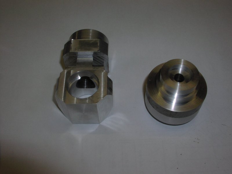
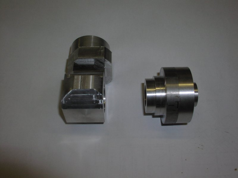
I spent this evening round with Brian and have got the first set of pictures and descriptions:-


1 & 2) Crank case parts at start of picture taking - some work done
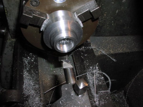


3) Front housing threaded and having the back ballrace and plain section machined
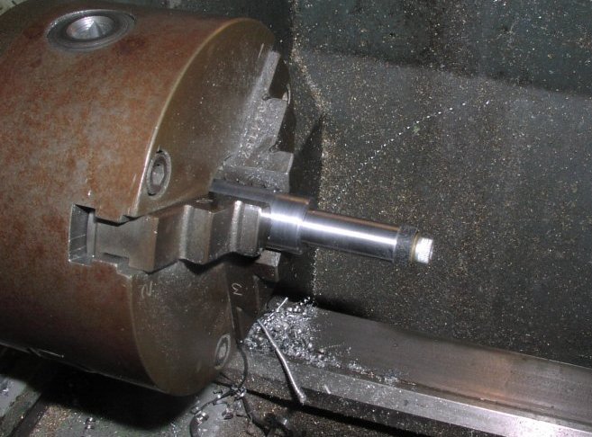


4) Machining fixture for the front housing. The location diameter is machined and not removed from the chuck the crankcase is slid on and the cap screw tightened The dark bit under the screw is hard rubber and is squeezed to grip the case to drive it when machined.
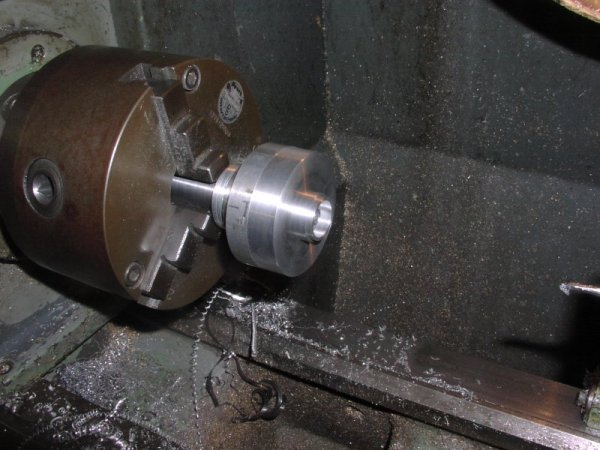


5) On the fixture machining the front ballrace housing and the outside nose
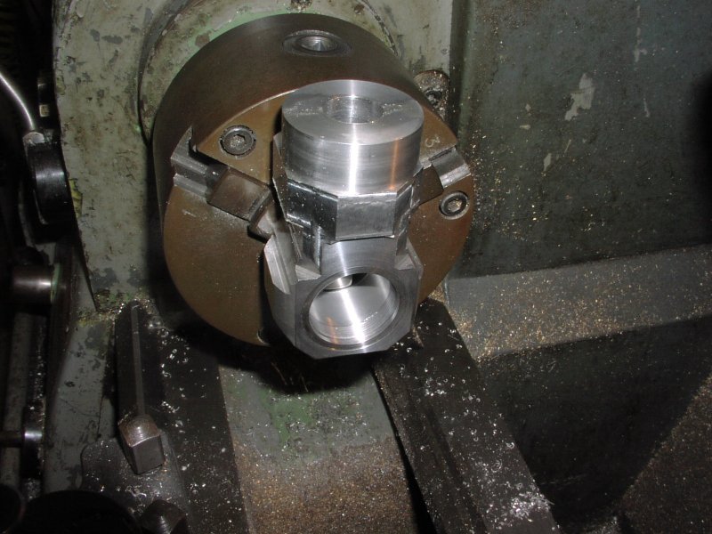


6) Machining the front face and the female thread and c/bore
the main bore was machined in the milling machine with a boring head
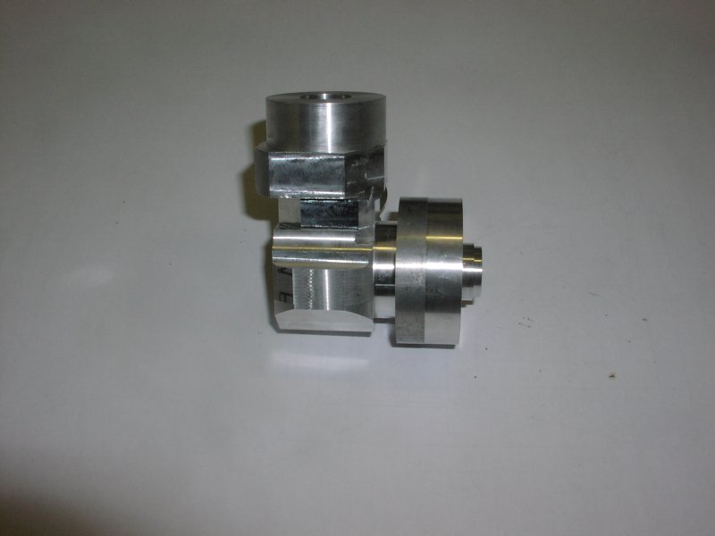


7) The 2 parts of the case screwed together with Loctite high
temperature retaining compound
Note: The o/d of the front housing and the front face were skimmed when the ballrace housing were being done so that these faces could be used as location faces for the next operations
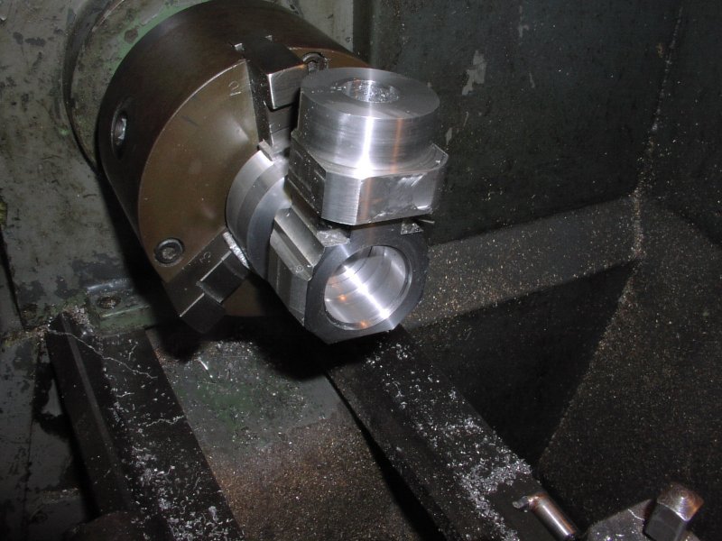


8) Set up to machine the back bores for the crankshaft, the clearance for the conrod, the oring c/bore on the back and face off for the backplate
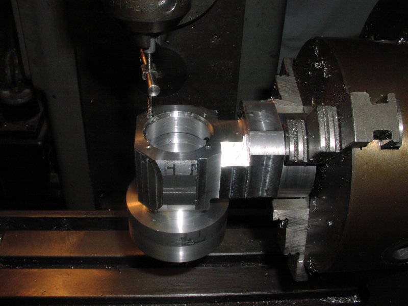


9) Set up in the dividing head on the milling machine to do the backplate mounting holes as these will be needed to mount the crankcase for further machining
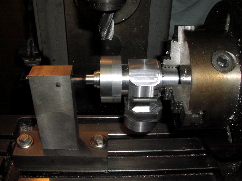


10) Set up in the dividing head ready to rough out the crankcase and front housing the case is mounted on a false backplate and the front is supported by a accurate pin located on the front ballrace housing and the plain 12mm bore this pin will be used to dial off to do some tricky machining later
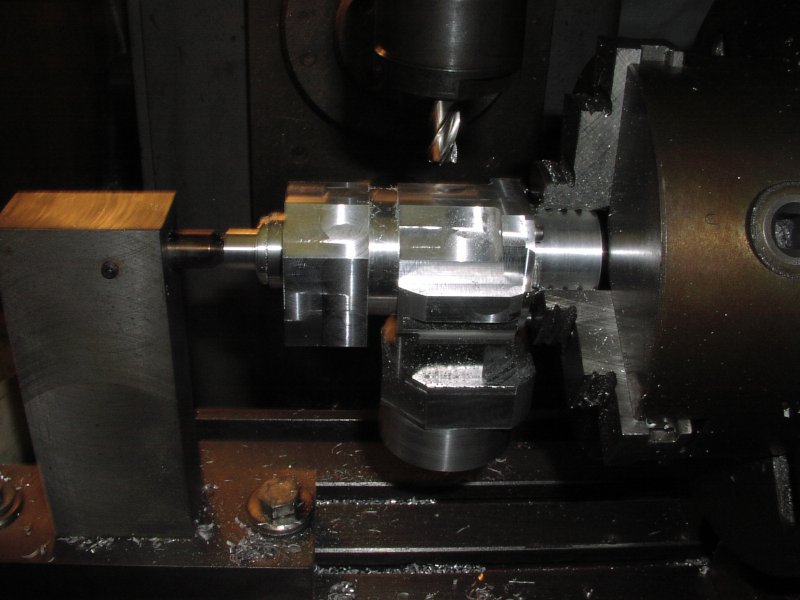


11) Roughing out the crankcase - the mounting lugs are taking shape and a lot of material has been removed from the case
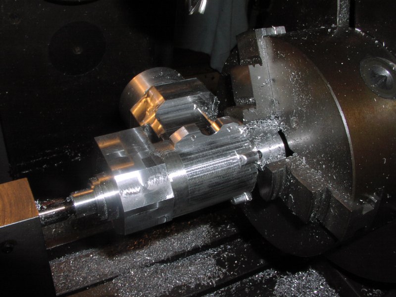


12) Mounting lugs finished and the crankcase shape machined. The backplate screw lugs are machine with hand ground form tools. The mounting holes in the lugs are positioned with great accuracy as they become the main location for hte machining of the inside of the upper crankcase
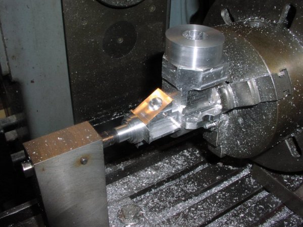


13) The front housing webs are machined to thickness but left full width to use as datums later. next the spraybar hole is drilled then the venturie top surface is machined with the dividing head tilted to 30° then the venturie hole is machined relative to the spraybar hole by putting a pin through it and wobbling off it.
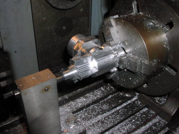


14) Finishing the webs and removing anything that doesn't look like a stunt engine
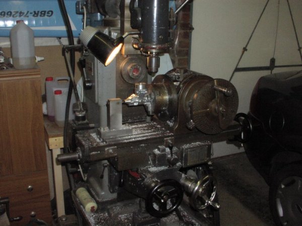


15) The milling machine - no digital readout need apply - the dividing head is a proper solid tool.
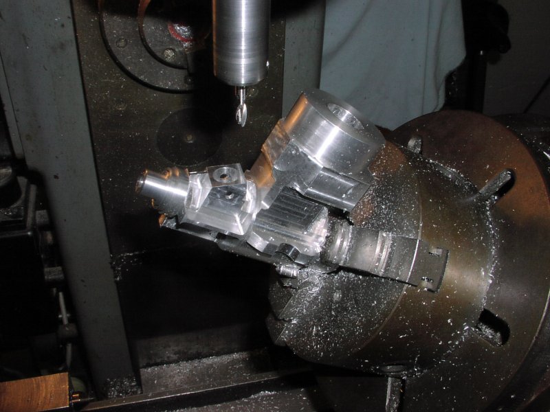


16) More venturie internal and external machining

Dallas Hanna · Jan 23, 2008 07:05 PM

#1 source
Looking good Mike. Isn't it great to see what can be done with manual machines and a competent operator. Keep us up-to-date with the progress.

HH

Warren · Jan 23, 2008 09:03 PM

#2 source
Mike,

That's amazing work !! Hard to comprehend the amount of work that goes in to a bar stock engine. Now we understand why the prices are up there.

Thanks for taking the time to post the pics and captions....very interesting reading. Will look forward to more.

Cheers.

Warren Wagner

Proparc · Jan 23, 2008 09:03 PM

#3 source
Amazing
Milton Graham\Proparc

Randy Powell · Jan 23, 2008 09:18 PM

#4 source
I've milled stuff for friends and they always seem amazed when I tell them the part takes 10 minutes to make. It's the setup that takes all the time. It's why I like to do more than one part if I'm going to do it at all. As you can see, a project like this one takes many operations and a lot of setup. To say nothing of more skill than I've got.

Sure looks cool.


-------------------------------------------------------------------------------------------------------
Some days it seems like a coin toss between George Orwell and Monty Python...

rj99891 · Jan 23, 2008 09:44 PM

#5 source
Now this is REAL builder of the model rule stuff! The rest of us have already fallen prey to ARF motors!

bob

Proparc · Jan 24, 2008 05:15 PM

edited#7 source
>Now this is REAL builder of the model rule stuff! The rest of
>us have already fallen prey to ARF motors!
>
> bob

You are right about that one. This guy is making even us hardcore builders feel ashamed!!


Milton Graham\Proparc

Giffy · Jan 23, 2008 10:35 PM

#6 source
Was the screw on front end done to save mill work on a bigger block of metal a one piece case would need? Just wondering because the boss for the threads might make it heavier. The barstock engines I've made were one piece cases but, they were small .049 engines.

Will the transfers be milled in the case? I'd like to see if the set up for that is the same way I did it.

Nice mill work on the bottom of the case and the rear cover lugs BTW.

Giffy