Stuka Stunt Control Line Forum
Archive, 2000–2021 · recovered from the Internet Archive
Forums › Stuka Stunt Main Forum

New stunt engine build part 2 picture set

Stuka Stunt Main Forum · 18 of 18 known posts recovered

pipemakermike · Feb 09, 2008 09:11 AM

edited#0 source
The build of the new stunt engine has moved on considerably since the last set of pictures.The crankcase is now finished and the crankshaft is well advanced. I have added a link to the last instalment:- First set of pictures]


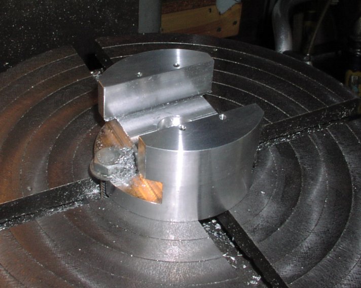
1)Now Brian is ready to machine the cylinder internal and external diameters. This is the fixture Brian has made to mount the crankcase both on a rotary table and in the chuck of the lathe. The fixture has a spigot locating in the centre hole of the rotary table. This rotary table is a very old but well made unit that has seen a lot of use and was showing the scars. Brian has skimmed the surface of the table and also remachined the centre hole to get the accuracy he demands.
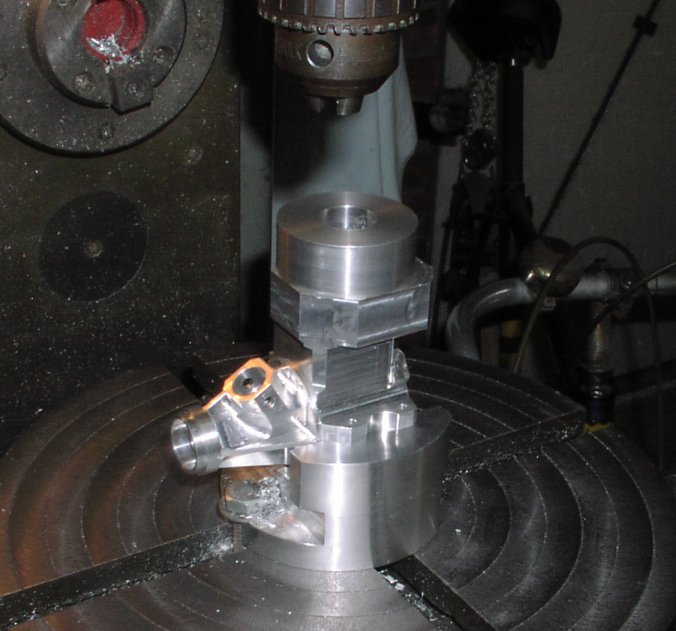


2) The engine is just standing in the fixture showing showing where it will fit when it is returned to the Miller after the machining of the internal bores that is the next operation.
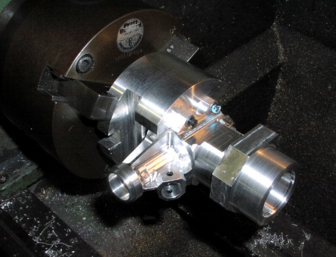


3) The same fixture is fitted to the lathe so that the round parts of the cylinder can be machined. As shown here the internal bores are finished and the transfer port outside shape has been turned (the front part of the crankcase behind the venturi).
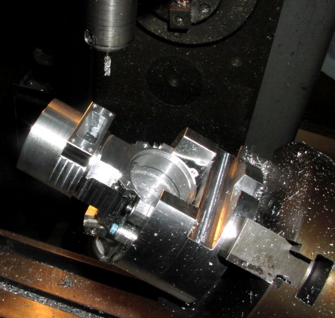


4) The exhaust port has been machined on the outside with the dividing head horizontal. Now the head has been tilted up to finish off the internal exhaust port machining (the upper face).
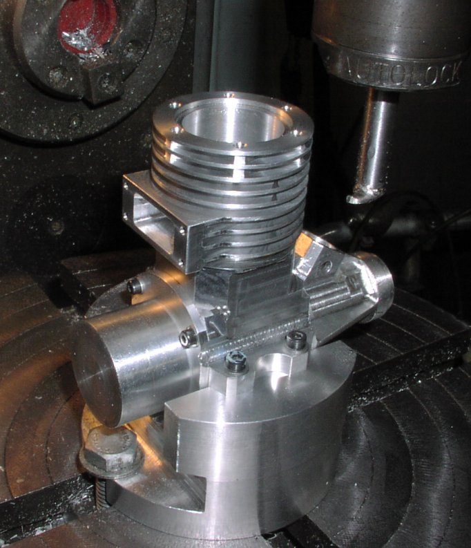
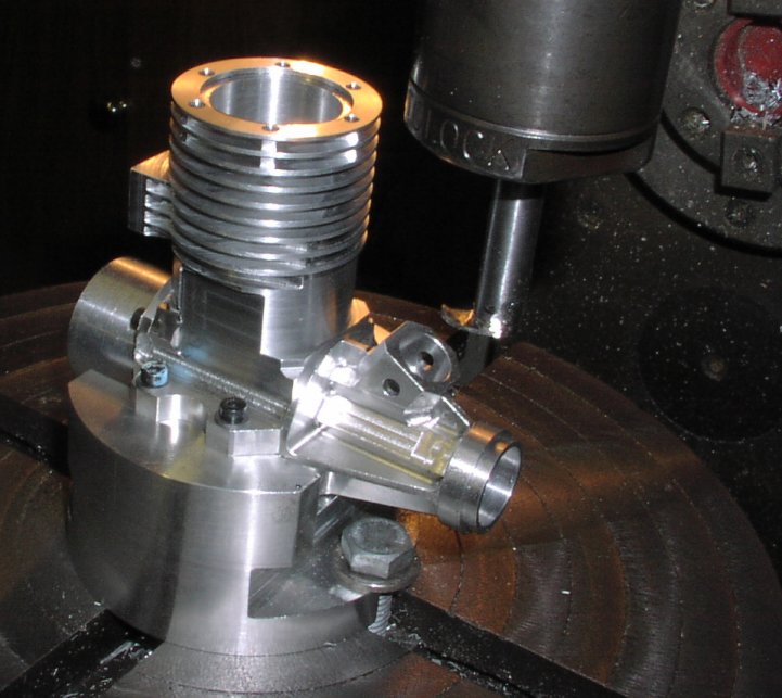


5) The case is now on the fixture mounted on the circular table and the fins are being machined. The tool is specially made for this engine to get the correct radius. Note it worked best when climb milling and all the slots were cut to depth in a single cut. This gave the best finish and the least chatter. Another trick Brian has used is to fit the dummy backplate fixture to the case to give even more stiffness to the case whilst machining.
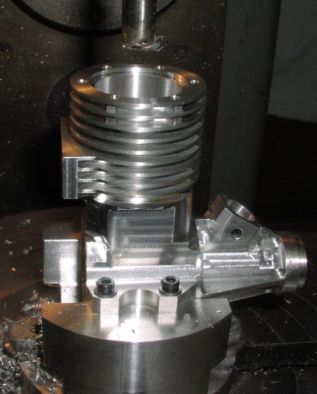
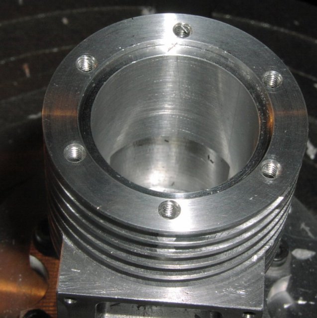


7) Machining the transfer port. This is the tool that Brian used - a single point tool with the largest shank that will allow the radius required for the internal port.
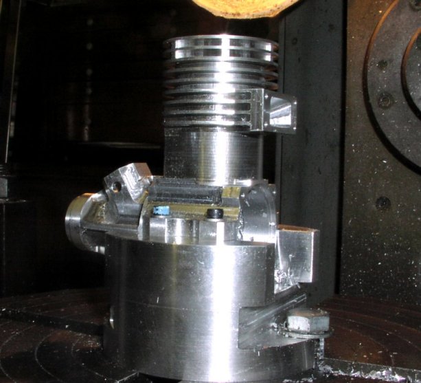


9) The outside of the case below the exhaust port is now machined.
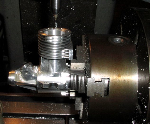


10) The conrod clearance groove has been machined by rotating the case and using another Brian's custom tools.
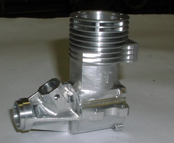
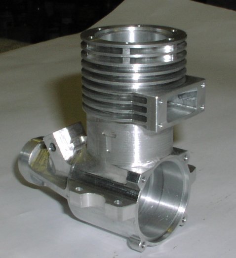
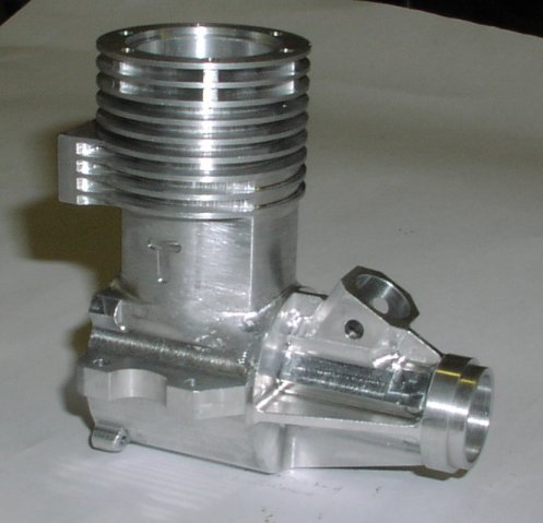
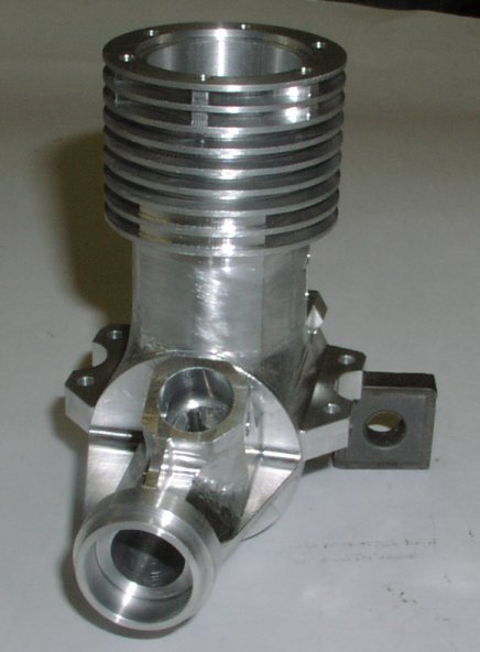


11) The case is now finished and any of the little hand fettled areas where machining is impossible have been dremel'd.
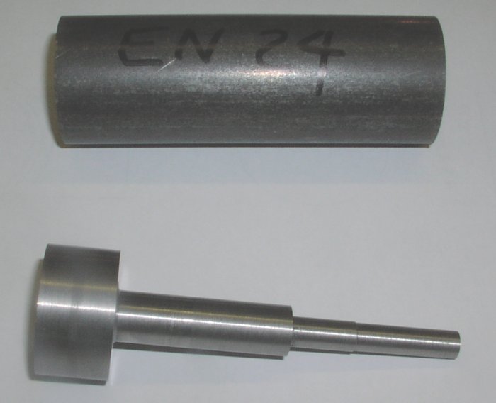


12) The crankshaft is made from a piece of EN24 A hardening carbon steel. as shown here the billet has been roughed out to plus 1mm all over to allow for any movement in the steel. (EN24 is a high quality, high tensile, alloy steel . Usually supplied readily machineable in ‘T’ condition, it combines high tensile strength, shock resistance, good ductility and resistance to wear. EN24 is a (1.5% Ni,Cr,Mo) steel in US equivalent to SAE 4340)
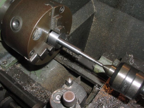


13) The roughed out shaft now has a centre in the end and is turned to plus 0.3mm ready for hardening.
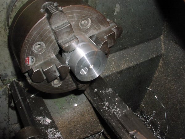
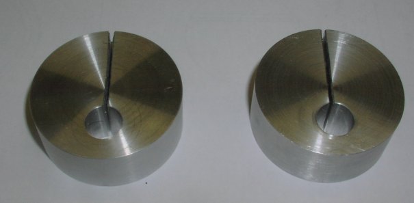


14) This is the machining of the 2 fixtures needed for machining the crank pin. There are two fixtures as the shaft mounting holes are different sizes. One is used for the machining when the shaft is plus 0.3mm and one for when the shaft is at the final size. The two are made from a single piece of aluminium and parted off when finished thus ensuring that the offsets are identical.
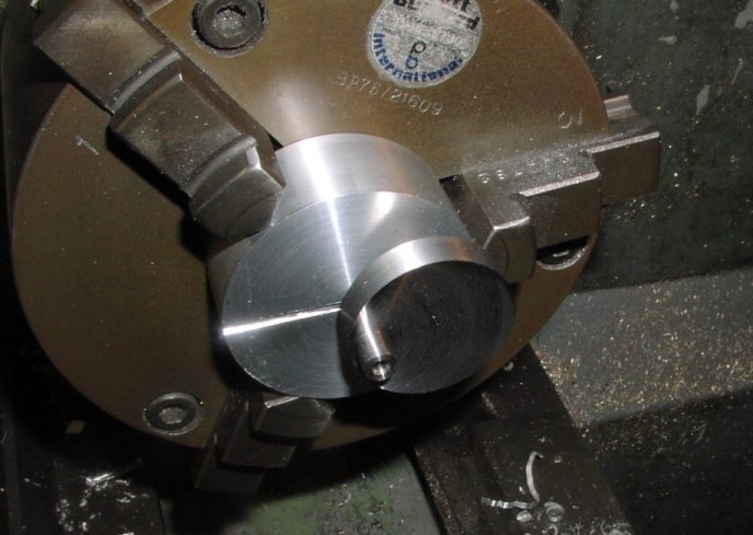


15) Using the roughing fixture for machining the pin.
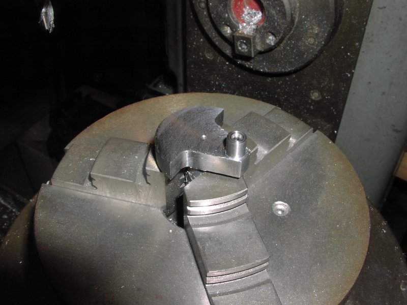


16) Machining the crankshaft web. The crankshaft is fitted to the dividing head for this job and the horizontal flats are machined accurately to use as datums for setting up the shaft for the next operations
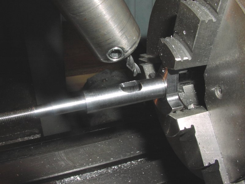


17) Machining the inlet port in the crankshaft. The bore has been drilled previously. The machining is done with the milling machine head set over at 30° so that the crankshaft is parallel to the bed enabling the crankshaft to be supported with a centre (not shown)
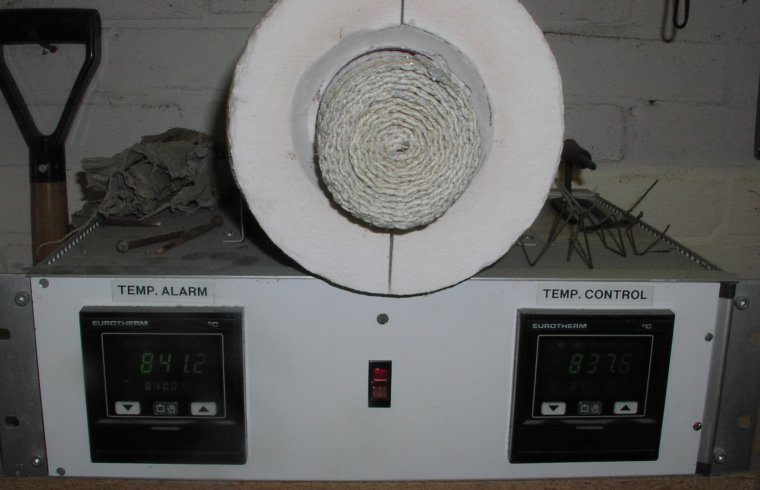


18) This is Brian's home made muffle furnace that he uses for all his heat treatment. it should be capable of working up to 1000°C.
The shaft was heated to 840°C then quenched in oil. Tempered to 180°C and quenched in oil.
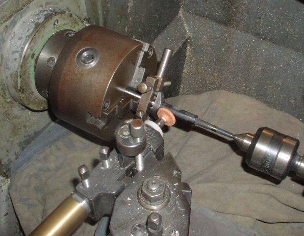
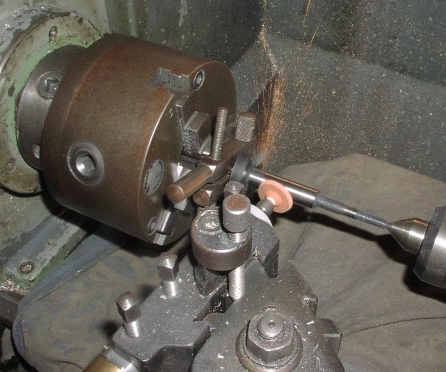


19) The shaft is set up in the lathe for the final grinding to final size. The power is a Dremel driving a custom made toolpost grinder.
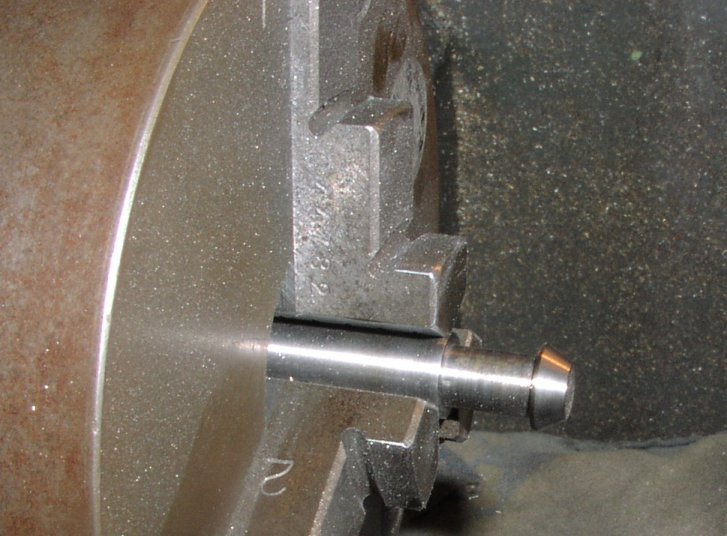


20) This is the centre pin in the chuck used for mounting the shaft turned to allow the driving dog to clamp on it and the crankpin.

Randy Ryan · Feb 09, 2008 09:37 AM

#1 source
GREAT shots Mike, I love to see other guys setups.
I assume Brian has a CNC machine or at least had the outside of the case CNC machined?

Randy Ryan <><
AMA 8500
SAM 36
BO all my own M's

pipemakermike · Feb 09, 2008 09:53 AM

edited#2 source
Hi Randy

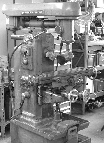
No CNC, No Digital readouts, in fact nothing that wasn't available in the 1950's Not even a set of digital calipers! Just a solid milling machine, an Elliot, with a solid universal dividing head and a solid rotary table. Even the lathe is from the 60's a Colchester Bantam possibly a Mk 1 although Brian thinks it might be a Mk2 with a Mk1 tailstock.
I even had to lend him my digital camera to do the pictures!
Brian is a remarkably skilled machinest.


captcurt · Feb 09, 2008 10:19 AM

#3 source
They really know how to train toolmakers in England Randy...you know that!

This is a superb photo essay of what it takes to make one of our engines. What beatiful work. Thanks to Brian and Mike for allowing us to share.

Curt

Randy Ryan · Feb 09, 2008 02:34 PM

edited#4 source
Tremendous feat of manual interpolation!!! Hmmmm, someone could take that the wrong way.

How many hours in the outside of the case Mike, any idea?

Randy Ryan <><
AMA 8500
SAM 36
BO all my own M's

Steve Helmick · Feb 09, 2008 03:09 PM

#5 source
I'm very impressed with the engine work, and I like the lathe. I'd take a Bridgeport mill over that Elliot in a heartbeat, tho I don't consider the Bridgeport to be wonderful. Brian should be proud of his new stunt donk. I hope it works as intended. Steve

Steve Helmick
Renton, Washington
USA

DW · Feb 09, 2008 04:00 PM

edited#6 source
Very impresive Mike! How does he know where to dill the hole in the crankshaft for the intake?
Thanks
dwayne
Wings on strings forever!

pipemakermike · Feb 10, 2008 06:25 AM

edited#13 source
Hi Dwayne

The design is to machine the crankshaft inlet exactly on the centreline of the crankpin so that it assists in the balancing of the engine.

Randy Powell · Feb 09, 2008 04:05 PM

#7 source
I'm always amazed at talented machinists. I dink around with a mill to do small parts and such, but I'm no machinist and know it. But I'm always in awe of really good manual machinists. Amazes me every time.


-------------------------------------------------------------------------------------------------------
Some days it seems like a coin toss between George Orwell and Monty Python...

Dr Spark · Feb 09, 2008 06:24 PM

#8 source
I can only imagine the level of anxiety during the final stages of machine work. One little slip and........

My poor heart couldn't take that kind of treatment.

Floyd in OR

GLBahrman · Feb 09, 2008 10:10 PM

edited#9 source
neat..you lost me on the description of picture no. 20
Greg L. Bahrman

Steve Helmick · Feb 09, 2008 11:28 PM

edited#10 source
Greg...the pin in Photo 20 is being used in Photo 19, just as shown in pic 20. The drive dog is clamped in the stepped down area behind the conical "center". The cone runs in the hole of the crank, which no doubt has a chamfer to match the cone. I'm interested in the use of the Dremel for crank grinding! More info on that would be cool... [photo not recovered: sipcof.gif] Steve

PS: Dr. Spark...there's a surprising amount of stress in the work of machining. Crappy drawings from engineers are a significant part of it!

Steve Helmick
Renton, Washington
USA

pipemakermike · Feb 10, 2008 04:02 AM

edited#11 source
Hi Steve

You are right on the button about the centre. and re the drawings, Brian has the real advantage of doing his own drawings and he is also a really good if very old fashioned draughtsman.
I'll ask Brian if he has any drawings of the Dremel mounting. I do know that it has a system to take out any backlash in the bearings to improve accuracy.

cfrizell · Feb 10, 2008 05:17 AM

#12 source
Wow - I just loved all those photos!

I did some training as a Toolmaker way, way back when I was 19 and working on the copper mines in Zambia, so I really appreciate the maching. Now, I doubt I could even drive a lathe [photo not recovered: cry.gif]

Charles

DMoon · Feb 10, 2008 12:00 PM

#14 source
That is so cool! I am so jealous!

What size will it be?

How long does it take to make something like this?

Doug Moon

Aerowrench · Feb 10, 2008 01:28 PM

#15 source
>snip<
>PS: Dr. Spark...there's a surprising amount of stress in the
>work of machining. Crappy drawings from engineers are a
>significant part of it!
>
>Steve Helmick
>Renton, Washington
>USA

Beautiful work!! Alot of the machinist today can't do the math required for angle cuts, sad.
Working as an Overhaul Mechanic for an Airline, I've had to be the liaison between the hangar floor and the machine shop. A Diplomat on some occasions, LOL.
-Doug

GLBahrman · Feb 10, 2008 03:23 PM

edited#16 source
Got it...Thanks Steve....I see the dog driving the crank pin and the pin in picture 20 is just the other crank center at the weight end along with the tail stock center.
Greg L. Bahrman

Randy Ryan · Feb 10, 2008 05:12 PM

#17 source

>PS: Dr. Spark...there's a surprising amount of stress in the
>work of machining. Crappy drawings from engineers are a
>significant part of it!
>
>Steve Helmick
>Renton, Washington
>USA

I RESEMBLE THAT REMARK!!!!

Actually what Steve says is sadly true, most, but not all engineers and CAD detailers of today have near zero understanding of the machining process. The worst part is, they don't care either.

Randy Ryan <><
AMA 8500
SAM 36
BO all my own M's