The design and detailing (all by hand with a pencil) took about a week - For Brian this is about 20 hours at the drawing board plus a lot of thinking time.
The project so fat has taken 5 weeks elapsed time and Brian aims to spend about 20 hours per week actually making the bits.
I have added a link to the last installments:-
First set of pictures]
second set of pictures]
I have pictures of the piston and the spinner nearly ready
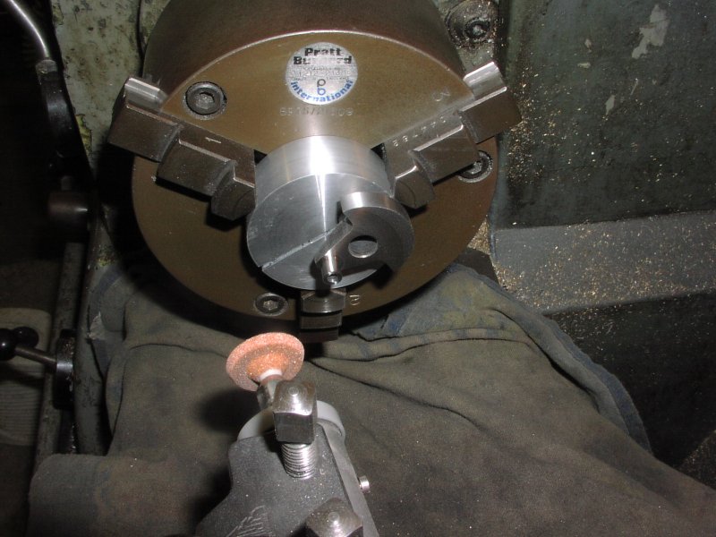
Final grinding of the crank pin in the lathe
BTW I checked with Brian and he doesn't have any drawings for the toolpost grinder. He made it from simple hand sketches and some "design on the fly"
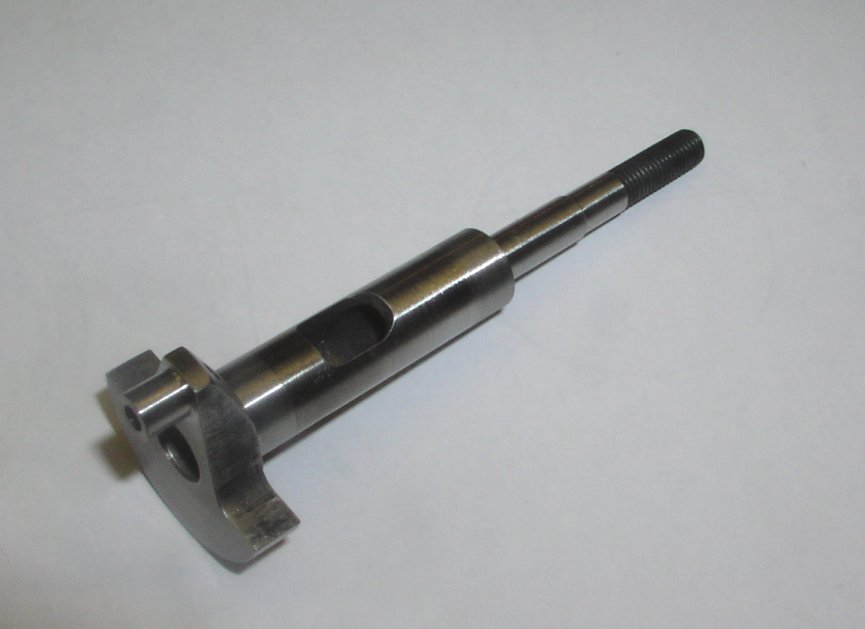
Crankshaft finished - the ballrace fit was finally lapped to get the interference fit.
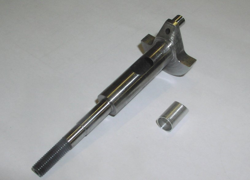
Light aluminimum insert is fitted to the front of the axial hole in the crankshaft to fill the end of the hole and to flare the end of the inlet.
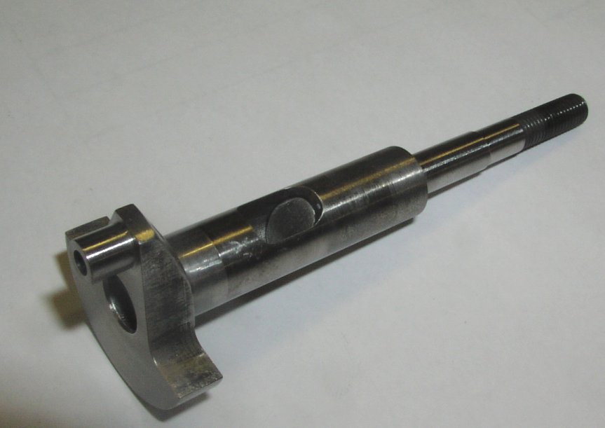
Here you can see it fitted into the shaft. locktite is used to fix it in place.
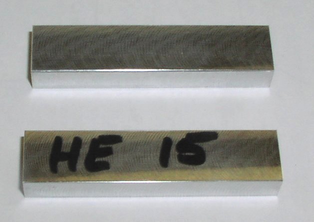
Conrod blanks milled to 1mm over size all round. Brian made 2 so as to have a spare.
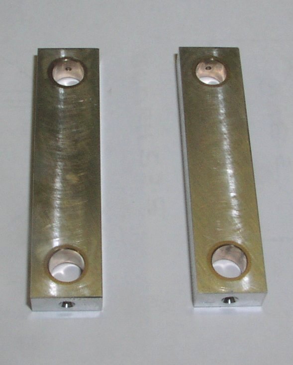
Conrod blanks drilled and fitted with the phosphor bronze bushes.
The holes are drilled Ø7.5, the bushes are pressed in and the blank is then returned to the mill to ream the bearing inner diameters and the blank is then milled down to final thickness.
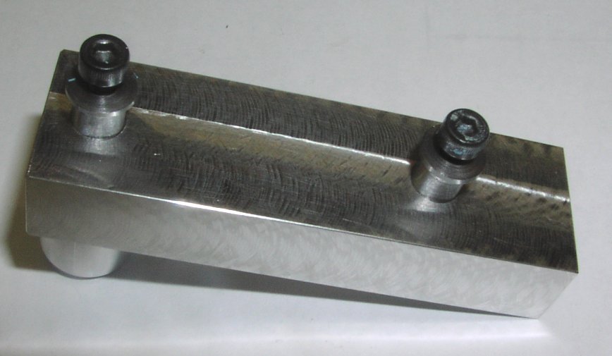
Here is the fixture for machining the conrod to shape.
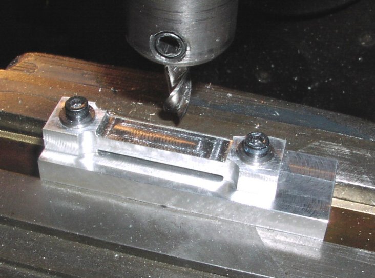
8 machining the sides and the top and bottom.
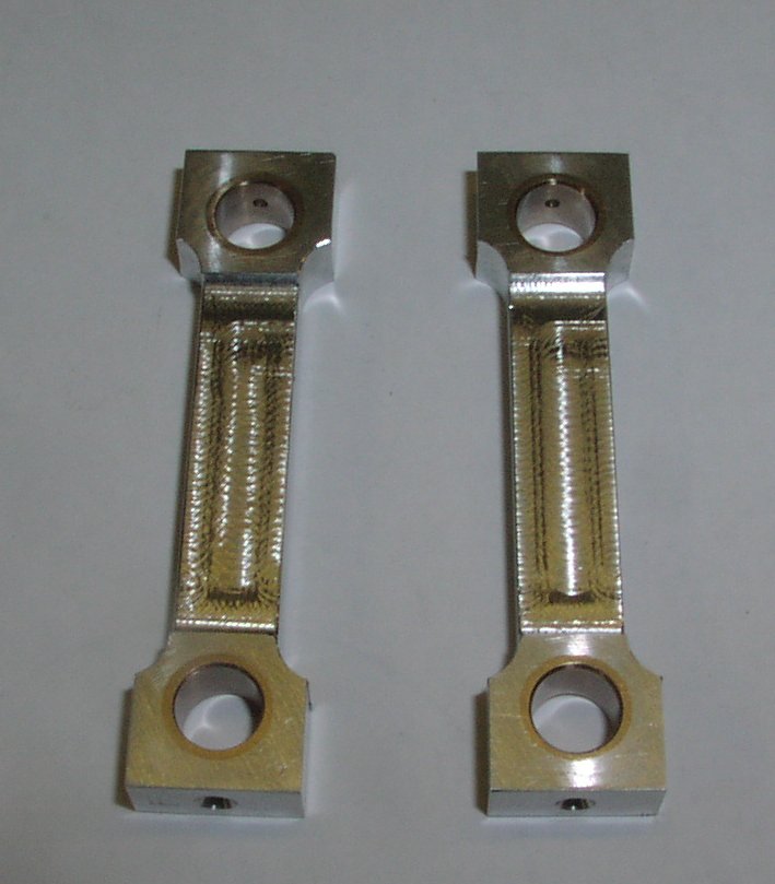
Basic rods with all the simple milling completed - just the round ends to machine.
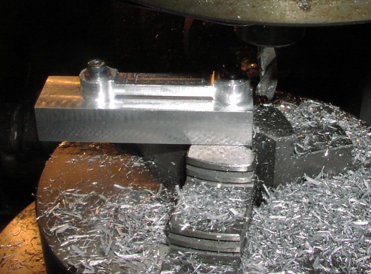
Fitted in the chuck of the dividing head for shaping the ends.
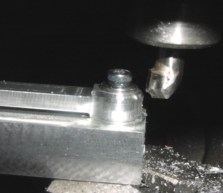
Radius cutter - home made of course for finishing the ends
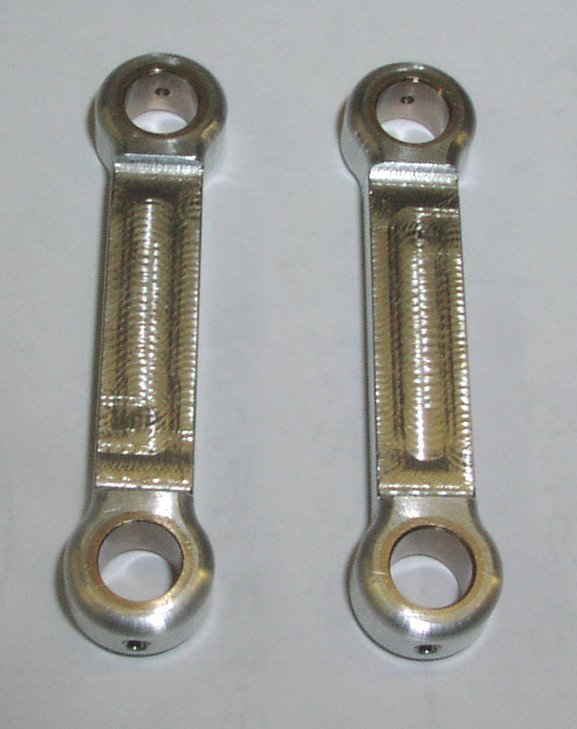
Finished rods.